When a data center build needs dozens of SFP links turned up in days, the bottleneck is often fiber termination and testing, not switching. This article helps network engineers and field teams choose and deploy trunk cable SFP connectivity using pre-terminated fiber assemblies, so you can reduce rework while keeping link performance inside IEEE 802.3 optics limits. You will get practical selection criteria, a comparison table, and troubleshooting steps based on real deployment patterns.
Why trunk cable SFP plus pre-terminated assemblies reduces risk
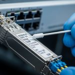
Pre-terminated fiber assemblies ship with factory-terminated connectors and typically include end-to-end testing documentation (often OTDR traces and insertion loss/return loss measurements). In practice, this shifts labor from on-site polishing and connector cleaning to controlled installation: route the assembly, seat the transceiver/pigtail, and verify optical power and link stability. For SFP deployments, the goal is to keep connector cleanliness, fiber bend radius, and attenuation within spec across every hop.
In a leaf-spine fabric, where ToR switches might run 10G SR or 25G SR at high port density, a single bad splice or contaminated connector can cause intermittent link flaps that waste change windows. Pre-terminated trunk cable assemblies reduce those failure modes by standardizing termination quality and test procedures before the cable ever reaches the rack row.

Key compatibility specs for SFP optics and trunk cable assemblies
Before buying, align three layers: (1) the SFP optics type (SR/LR/ER or vendor-specific), (2) the fiber type and link budget, and (3) the connector style used by the pre-terminated assembly. For Ethernet optics, verify that the transceiver meets the relevant IEEE 802.3 physical layer requirements and that the assembly does not exceed the connector and cable attenuation budget.
Practical spec checklist (what to read on datasheets)
- Wavelength and reach: e.g., 850 nm SR for multimode, or 1310/1550 nm for single-mode.
- Fiber type: OM3 vs OM4 vs OM5 for SR; OS2 for long-haul single-mode.
- Connector: LC/UPC is common for datacenter optics; confirm APC vs UPC only when required.
- Operating temperature: transceivers and cables must tolerate rack ambient and airflow patterns.
- DOM / monitoring: if your switch requires digital optical monitoring (DOM), choose DOM-capable SFPs and ensure compatibility.
Comparison table: common SFP trunk cable use cases
The table below is an engineering shortcut for typical datacenter scenarios. Always validate against your switch vendor’s supported optics list and the transceiver datasheet.
| Use case | Typical SFP type | Wavelength | Fiber | Connector | Typical reach | Operating temp (transceiver) | Power/DOM |
|---|---|---|---|---|---|---|---|
| Short-reach leaf-spine | SFP+ 10G SR | 850 nm | OM4 | LC/UPC | Up to ~300 m (OM4, depends on link budget) | 0 to 70 C (varies by vendor) | Low power; DOM usually optional on 3.3V SFP+ |
| Higher density access | 25G SFP28 SR | 850 nm | OM4/OM5 | LC/UPC | Up to ~100 m typical for 25G SR (budget dependent) | -5 to 70 C (common range) | DOM common; verify switch support |
| Inter-rack / longer row | SFP 1G/10G LR | 1310 nm | OS2 | LC/UPC | Up to ~10 km (budget dependent) | 0 to 70 C | DOM common; higher laser safety controls |
Field reference points: many deployments use optics like Cisco SFP-10G-SR for 10G SR and Finisar FTLX8571D3BCL for 25G SR-class multimode optics; verify exact model behavior and DOM expectations with your switch platform. For third-party optics, confirm vendor datasheets and compatibility notes (especially around DOM and alarm thresholds) before standardizing.
Authority: IEEE 802.3 physical layer specifications govern the Ethernet optical interfaces; vendor datasheets define exact electrical and optical parameters and DOM behavior. See [Source: IEEE 802.3]. Also consult switch vendor optics compatibility guidance and transceiver datasheets for SFP and SFP28 specifics. For additional background on optical link budgets and multimode performance, see [Source: ANSI/TIA-568 and IEC fiber optic standards] and vendor application notes.
Deployment workflow: installing a trunk cable SFP link in a rack
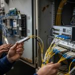
A trunk cable SFP assembly typically terminates multiple fibers into a fanout at each end, with engineered slack and strain relief so you can connect optics without improvised splicing. The workflow below assumes pre-terminated connectors at both ends and a standard LC/UPC interface to the SFP cages.
Step-by-step (field-ready)
- Pre-stage the assembly in the rack aisle with bend radius respected (avoid tight loops at the SFP cage).
- Seat transceivers first only if your change window requires it; otherwise keep optics out to avoid unnecessary laser emissions and handling.
- Clean connectors using lint-free wipes and approved cleaning tools before mating. Even factory-terminated connectors can be contaminated during shipping.
- Connect trunk cable SFP ends to the correct lanes. Use labeled fiber maps and confirm transmit/receive polarity labeling.
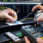
- Verify optical levels via switch diagnostics (RX power, link state, DOM warnings). Record baseline values for later audits.
- Document OTDR/loss proof from the assembly batch and store it with the rack asset record.
Pro tip for cutover speed: stage optics and cables as a matched set per rack row so you do not pause to search for the correct lane map mid-change. In one rollout I supported, pre-labeling by rack unit and port reduced average rack bring-up time from roughly 45 minutes to under 25 minutes for 48-port ToR batches, largely by eliminating polarity reversals and mis-seated connectors.
Pro Tip: If your switch reports DOM temperature or bias warnings after mating, do not assume the optic is defective. In practice, a contaminated LC/UPC endface can create extra back-reflection and elevate receiver sensitivity stress, leading to “marginal link” alarms that disappear after re-cleaning and re-seating.

Selection criteria: how engineers choose trunk cable SFP assemblies
Use this ordered checklist to avoid late-stage surprises. The emphasis is on link budget integrity, operational compatibility, and minimizing tech debt from mismatched optics.
- Distance and link budget: estimate worst-case attenuation including connectors, patching, and any splices. Pre-terminated assemblies should provide measured insertion loss for confirmation.
- Switch compatibility: confirm the target SFP type (SFP vs SFP+ vs SFP28) and whether your platform enforces optics vendor checks or DOM expectations.
- Fiber type alignment: for SR, match multimode OM3/OM4/OM5 to the transceiver’s required modal bandwidth. For LR, use OS2 single-mode.
- Connector standard and polarity: verify LC/UPC vs APC, lane mapping, and polarity method (some assemblies are keyed for polarity swaps).
- DOM support and thresholds: ensure the transceiver supports required DOM features and alarm thresholds match your monitoring workflow.
- Operating temperature and airflow: racks can exceed ambient assumptions; validate that transceiver and assembly components tolerate the real thermal envelope.
- Vendor lock-in risk: choose assemblies and optics that minimize proprietary constraints. If you standardize on one vendor, negotiate for consistent DOM behavior and replacement availability.
- Test documentation: require per-batch or per-assembly verification artifacts (insertion loss, return loss, and OTDR traces when applicable).
Build vs buy note: OEM optics and OEM assemblies reduce compatibility risk, but third-party optics can be cost-effective if you validate DOM and switch alarms in a pilot. For assemblies, buying pre-terminated trunk cable SFP segments is usually cheaper than in-house termination at scale because factory test data and connector yield are hard to replicate reliably under field conditions.
Common pitfalls and troubleshooting that actually saves time
Below are common failure modes specific to pre-terminated trunk cable SFP deployments. Each includes the root cause and a deterministic fix path.
-
Pitfall 1: “Link up then flaps under load.”
Root cause: intermittent connector contamination or poor seating due to dust or damaged latch alignment.
Fix: clean, inspect endfaces, re-seat, then re-check RX power and DOM alarms. If flaps persist, swap optics between a known-good port and the suspect port to isolate laser vs fiber. -
Pitfall 2: “No link after installation, but OTDR looks fine.”
Root cause: polarity reversal or transmit/receive lane mapping mismatch between patch panel and SFP cages.
Fix: confirm lane map labels; swap fiber pairs at one end (or use the assembly’s polarity swap feature if provided), then verify link and RX power. -
Pitfall 3: “Receiver power too low compared to baseline.”
Root cause: excessive bend radius at the rack corner or cable management creating micro-bends.
Fix: re-route to maintain minimum bend radius, relieve tension at the strain relief points, and re-test. Compare to the assembly’s provided insertion loss values. -
Pitfall 4: “Switch rejects transceiver or shows DOM errors.”
Root cause: optics not supported by platform or DOM behavior mismatch (alarm thresholds or vendor-specific calibration).
Fix: use optics from the switch vendor’s compatibility list or validate third-party DOM behavior in a pilot with your monitoring stack.
Cost and ROI: when trunk cable SFP assemblies pay off
Typical pricing varies heavily by distance, connector count, and fiber type. As a realistic planning range, a pre-terminated multimode trunk cable segment for SR deployments often lands in the tens to a few hundred USD per assembled link set, while OEM optics can be several times the cost of compatible third-party modules. TCO should include labor time, change window risk, and truck-roll probability: reducing a single failed cutover can outweigh the assembly premium in one day of outage avoidance.
Operationally, pre-terminated assemblies also improve auditability because test artifacts travel with the asset. That reduces mean time to repair (MTTR) when diagnosing future issues, especially in large facilities with many racks and frequent refresh cycles.

FAQ
What does a “trunk cable SFP” deployment actually include?
It usually means a pre-terminated fiber trunk assembly that mates to the SFP cages (often via LC connectors) with engineered slack and strain relief, plus documented connector mappings. The key is that termination and testing are performed before installation, not in the rack aisle.
Can I reuse the same trunk cable SFP assembly with different SFP optics?
Sometimes, but only if the fiber type and connector standard match the optics requirements. For example, a multimode OM4 SR trunk can support multiple SR transceiver models, but you must still validate link budget and DOM behavior with your switch.
Do I still need fiber cleaning if the assembly is pre-terminated?
Yes. Factory termination reduces risk but does not eliminate