Edge computing deployments move traffic from centralized data centers to warehouses, retail sites, and utility substations, often with constrained power, rugged enclosures, and tight maintenance windows. This article helps network and procurement teams specify the right transceivers for fiber network design when reliability matters more than lab-perfect optics. You will compare common 10G and 25G module options, translate IEEE-aligned electrical needs into practical procurement decisions, and avoid failure modes that show up after go-live.

Edge computing transceiver requirements that actually drive fiber network design
In edge environments, the transceiver is rarely the only decision; it is the hinge that connects your link budget, connector plan, and temperature envelope to your uptime goals. Most failures trace back to mismatched reach class, inadequate optical budget for the actual fiber plant, or modules that do not meet the host switch’s electrical and management expectations. IEEE 802.3 defines the physical coding and optical lane behavior for common Ethernet rates, but vendor-specific implementation details (DOM, baud rate quirks, and compliance modes) determine whether the link stays stable under real operating conditions. For procurement, the goal is to standardize module families while still matching the edge site’s distance and environmental realities.
Map your edge traffic and distance before you pick optics
Start with the edge topology: how many hops from switch to server, from ToR to aggregation, and from edge router to demarcation. Then measure or conservatively estimate end-to-end distance including patch cords, splices, and slack. A common procurement mistake is selecting a “reach” based on core fiber length only, ignoring that patch cords and connector pairs can consume a meaningful portion of the budget. If you do not have fiber test results (OTDR traces or at least end-to-end attenuation), plan for a conservative margin and require the vendor to support the application with documented link budget assumptions.
Choose the correct transceiver family for your Ethernet rate
Edge sites frequently standardize on 10G (SFP+) for cost-effective upgrades and 25G (SFP28) for next-gen bandwidth. When you move to 25G, you typically gain higher throughput per port and improve oversubscription headroom, but you must validate host support and power draw. For 100G and above, the modules usually change form factor (QSFP28/CFP2), and the connector and optics strategy becomes more sensitive to cleaning and transceiver lane mapping.
DOM and management expectations in remote locations
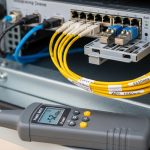
Digital Optical Monitoring (DOM) is a procurement requirement for edge sites because you cannot easily swap optics during business hours. Ensure the module supports DOM and matches the host’s expectations for diagnostics reporting. In practice, many field engineers use DOM thresholds to trigger early replacement before a link degrades; however, the DOM implementation can differ between OEM and third-party modules. If you are operating under a standardized monitoring stack, request sample reports from the vendor and validate alert behavior in a staging switch.
Temperature range and enclosure constraints
Edge deployments often run in industrial cabinets with restricted airflow. A “works in the lab” module may fail when the enclosure heats during peak operations. For fiber network design, treat the transceiver’s operating temperature as a hard requirement, not an afterthought. If your site experiences cold starts or seasonal swings, prefer modules with a wider operating temperature range and validate with accelerated thermal testing when possible.
Transceiver spec comparison: 10G SFP+ vs 25G SFP28 for edge fiber runs
Below is a practical comparison for common multimode and single-mode scenarios. Exact compatibility depends on the host switch and the transceiver’s compliance profile, but the table captures the procurement-critical specs you should request from vendors. For edge fiber network design, the key is matching the optics to the real plant: fiber type (OM3/OM4 vs OS2), core diameter, connector style, and the measured attenuation profile.
| Module type | Typical part examples | Data rate / standard | Wavelength | Reach (typical) | Connector | DOM | Operating temperature |
|---|---|---|---|---|---|---|---|
| 10G SR (multimode) | Cisco SFP-10G-SR, Finisar FTLX8571D3BCL, FS.com SFP-10GSR-85 | 10G Ethernet (IEEE 802.3) | ~850 nm | ~300 m on OM3, ~400 m on OM4 (class-dependent) | LC | Usually supported | Commonly 0 to 70 C (verify) |
| 10G LR (single-mode) | Vendor LR 10G SFP+ examples | 10G Ethernet (IEEE 802.3) | ~1310 nm | ~10 km (class-based) | LC | Commonly supported | Often wider than SR (verify) |
| 25G SR (multimode) | Vendor 25G SFP28 SR examples | 25G Ethernet (IEEE 802.3) | ~850 nm | ~70 m to ~100 m on OM4 (class-dependent) | LC | Commonly supported | Verify tight budget for edge enclosures |
| 25G LR (single-mode) | Vendor 25G SFP28 LR examples | 25G Ethernet (IEEE 802.3) | ~1310 nm | ~10 km typical | LC | Commonly supported | Verify for industrial edge |
When you are designing fiber network design for edge computing, SR vs LR is often a plant decision. If the edge site has existing multimode cabling, SR can reduce cost and simplify spares. If you are planning long runs to a demarcation point or crossing outdoor spans, LR on OS2 is frequently more forgiving and easier to scale, but it changes the fiber termination and cleaning discipline.
Pro Tip: Even when a module is “rated” for a reach, field failures often happen because connector end faces are not maintained. For SR optics, one contaminated LC connector can push received power below margin; require end-face inspection and cleaning logs as part of the acceptance checklist, not just installation day.
Procurement and supply chain reality: cost, lead time, and supply risk
Edge networks magnify supply chain risk because you need spares that match the deployed host firmware behavior. If your edge sites are distributed, you cannot rely on a single centralized depot for emergency swaps, so you should plan a spares strategy by module family and vendor qualification status. OEM modules often have predictable compatibility with Cisco, Arista, Juniper, and similar platforms, but third-party modules can be cost-effective if you validate DOM and link behavior in the same switch model.
Cost ranges and TCO considerations
Typical street pricing varies by volume and vendor qualification, but budget planning can use realistic ranges. In many enterprise edge refresh projects, 10G SFP+ SR modules often land in a mid-range price band, while 25G SFP28 SR modules can cost more per unit due to newer optics supply. LR modules on single-mode generally cost more than SR multimode options, and industrial temperature variants can carry a premium. Over a 3 to 5 year horizon, total cost is driven by failure rates, warranty terms, and the operational cost of downtime during replacement.
For TCO, include: (1) spares inventory carrying cost, (2) technician time for optics swaps, (3) validation effort for third-party optics, and (4) the cost of fiber testing (OLTS/OTDR) if you do not already have baseline results. A practical approach is to standardize on one or two module families for each rate and distance class, then qualify a limited set of suppliers to reduce lead time risk.
Lead time and qualification strategy
Edge deployments can be delayed by transceiver lead times, especially for specific DOM-capable variants and wide-temperature grades. To reduce delays, keep at least a minimum buffer stock for the most common distances: for example, SR for short horizontal links and LR for longer single-mode uplinks. Require vendors to provide traceability documentation and firmware compatibility notes where applicable. If you are using third-party optics, insist on a qualification plan that includes link stability under the host’s actual configuration and monitoring behavior.

Common mistakes and troubleshooting tips for edge fiber links
Most edge transceiver problems look like “random link flaps” or “no link,” but root causes are usually systematic. Below are frequent failure modes that procurement and field teams can prevent with better fiber network design discipline and acceptance testing.
Selecting reach based on fiber length only
Root cause: The design ignores connector loss, splice loss, and patch cord attenuation, leaving insufficient optical power margin at the receiver. This is common when teams assume “300 m SR” means any 300 m of cable will work.
Solution: Require fiber test results: at minimum, document end-to-end attenuation and connector/splice counts. If you cannot test every link, add a conservative margin and prefer a higher reach class or single-mode LR with documented budget.
Mixing multimode and single-mode connectors or fiber types
Root cause: LC connector hardware can look identical, but the fiber core and optical mode behavior differ between OM3/OM4 and OS2. A mismatched plant can cause low received power and intermittent errors.
Solution: Enforce a labeling and verification process: confirm fiber type at both ends during install, and update as-built documentation. During acceptance, validate link error counters and run a sustained traffic test.
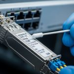
Contaminated fiber end faces and cleaning gaps
Root cause: Even new patch cords can carry residue from manufacturing or handling. In edge cabinets, vibration and repeated plug cycles increase contamination risk.
Solution: Implement a cleaning workflow: inspection with a scope, then cleaning with approved wipes and caps. Track cleaning actions in the installation checklist and keep spare inspection tools on-site.
DOM or compatibility mismatch between transceiver vendor and host switch
Root cause: Some hosts enforce stricter management thresholds or require specific DOM behavior. Third-party optics may report diagnostics differently, causing monitoring systems to misinterpret health.
Solution: Validate with a staging switch that matches the edge model. Confirm DOM visibility, threshold logic, and that the link comes up reliably after warm resets. If monitoring integration is critical, request DOM sample outputs from the vendor.
Temperature-induced performance drift in poorly ventilated enclosures
Root cause: Transceiver output power and receiver sensitivity can shift with temperature, especially for modules operating near their limits.
Solution: Verify operating temperature range and consider airflow improvements or enclosure sizing. If possible, log ambient temperature and correlate with link error counter trends.
Selection criteria checklist for fiber network design in edge sites
Use this ordered checklist during procurement and design review. It is intentionally practical: field teams typically need these answers quickly, and procurement needs them to lock pricing and lead time.
- Distance and fiber type: Confirm OM3/OM4 vs OS2, and account for patch cords, splices, and connector pairs.
- Ethernet rate and host compatibility: Validate SFP+ vs SFP28 support for your exact switch models and software versions.
- Optical reach class: Match SR vs LR to measured plant, not assumptions. Prefer higher margin for unmanaged edge links.
- DOM support and monitoring integration: Ensure DOM is enabled, readable, and compatible with your alerting workflows.
- Operating temperature: Select wide-temperature modules if edge enclosures experience extreme ambient conditions.
- Connector standard and cleaning readiness: LC vs other connector types, plus installation kit availability for end-face inspection.
- Vendor lock-in risk: Decide where OEM modules are mandatory and where qualified third-party modules are acceptable.
- Warranty, return policy, and RMA lead time: Edge networks need predictable replacement cycles.
- Spare strategy and stocking: Identify top module SKUs by site role (access, aggregation, demarcation) and keep buffer stock.

FAQ for edge computing transceivers and fiber network design
Q1: Should we standardize on multimode SR or single-mode LR for edge sites?
If the existing plant is OM3/OM4 with short horizontal runs and you can enforce cleaning discipline, SR SR modules can be cost-effective. For longer runs, outdoor segments, or uncertain link budgets, LR on OS2 typically reduces risk and simplifies scaling. In procurement terms, single-mode often means fewer “surprise” reach issues, but it can require more structured fiber plant planning.
Q2: What should we verify for host switch compatibility?
Verify that the host switch supports the exact transceiver form factor and rate (SFP+ vs SFP28) and that the transceiver is recognized as a compliant module. Validate DOM visibility and ensure link comes up reliably after warm and cold resets. If you use third-party optics, test in the same switch model and software train that runs at the edge.
Q3: How do we handle DOM and monitoring thresholds?
Require vendor documentation for DOM fields and confirm that your monitoring system interprets thresholds correctly. In staging, generate a controlled link degradation scenario if possible and confirm alert behavior. This reduces false positives and prevents missed early warnings.
Q4: Are third-party transceivers safe for edge deployments?
They can be safe if you qualify them rigorously: DOM behavior, link stability, temperature performance, and RMA terms. The risk is not theoretical; it shows up when a monitoring system or host enforcement logic behaves differently than expected. A limited supplier qualification plan is the best balance between cost and reliability.
Q5: What is the fastest way to troubleshoot a “no link” edge port?
Start with optics seating, then inspect and clean connector end faces, then verify fiber type and polarity. Next, check switch port diagnostics and DOM readings, and confirm the remote end transceiver matches the expected type. Finally, run a sustained traffic test and monitor error counters to separate physical issues from higher-layer problems.
Q6: What standards should we reference during design and procurement?
Use IEEE 802.3 for Ethernet physical layer behavior and vendor datasheets for optical parameters and DOM support. For fiber cabling practices, align your acceptance testing with recognized ANSI/TIA cabling guidance and require OTDR or attenuation test documentation when possible. These references help justify design margins and reduce disputes during commissioning.
For procurement-ready fiber network design in edge computing, the winning approach is disciplined plant measurement, explicit module qualification, and a spares strategy that respects lead times and RMA realities. Next, review your related cabling and acceptance testing process using fiber optic cabling acceptance testing.
Author bio: I have led transceiver and fiber procurement for distributed edge networks, working directly with field teams on acceptance testing, DOM validation, and RMA workflows. I translate IEEE-aligned optics requirements into purchase specs and lead-time plans that keep deployments on schedule.