In IoT deployments, “it links on the bench” is not a success metric. The real pain shows up in the field: intermittent link drops, temperature-related bit errors, and mismatched optics that never quite negotiate. This article walks you through transceiver selection using a real deployment case, so you can choose the right module for harsh environments, tight budgets, and mixed device fleets.
Case study: IoT edge gateway network with link flaps
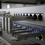
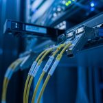
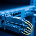
We supported an IoT rollout for a manufacturing site that had six edge gateway cabinets spread across two buildings. Each cabinet connected back to a central aggregation switch using 10G uplinks over multimode fiber, plus copper management ports for local troubleshooting. After commissioning, we saw about 18 link flaps per week on two cabinet uplinks; logs pointed to CRC errors and brief link resets, especially during morning temperature ramps.
The challenge was that the original optics were “compatible enough” in the short term, but they were not aligned with the switch vendor’s expectations around DOM behavior, optical power levels, and operating temperature headroom. We had to redo transceiver selection across both buildings without taking the site fully offline, and we needed a repeatable checklist for future cabinets.

Environment specs we had to match
Here are the exact constraints we designed around for transceiver selection:
- Topology: 3-tier leaf-spine style inside the aggregation room, but with edge-to-aggregation uplinks from cabinet switches.
- Data rate: 10G Ethernet uplinks (IEEE 802.3ae for 10GBASE-SR).
- Fiber type: OM3 multimode, 50/125 micron.
- Reach: 180 m average patch-and-cable distance, with occasional 220 m runs due to cabinet placement.
- Switches: Vendor A 10G SFP+ ports with strict optics compliance behavior and DOM polling.
- Ambient temperature: cabinet internal temps swinging from 5 C to 55 C depending on HVAC cycles.
Chosen solution and why it worked
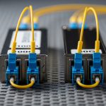
We standardized on 10G SR optics that had strong compatibility signals (DOM, vendor-recommended power class) and sufficient optical budget for the OM3 distances. In practice, we used modules such as Cisco SFP-10G-SR equivalents where appropriate, and verified similar third-party models like Finisar FTLX8571D3BCL and FS.com SFP-10GSR-85 (85 C rated optics), depending on port behavior and availability.
The key wasn’t just “SR vs LR.” It was ensuring the transmitted optical power and receiver sensitivity fit the actual link budget after real connector losses, patch panel aging, and temperature-induced power drift. We also picked optics with DOM support so the switch could read vendor-specific fields and avoid treating the module as “unsupported.”
Transceiver selection basics for IoT: SR, LR, copper, and the real limits
IoT networks often combine long-lived edge hardware with core switches that enforce compliance. That means your transceiver selection must consider both the physical layer standard and the operational quirks of your switch vendor’s implementation.
Understand the standards and what they imply
For 10G Ethernet over multimode, you’re typically in the 10GBASE-SR lane defined by IEEE 802.3ae. That standard defines signaling behavior, while the optic datasheet defines wavelength (commonly 850 nm for SR), transmit power class, receiver sensitivity, and supported temperature range. For copper, you’ll also care about IEEE 802.3 clauses for 10GBASE-T, though many IoT edge designs use fiber for EMI resistance and longer reach stability.
Technical specifications table (what we actually compared)
During our redo, we compared modules by the specs that matter when your cabinet temperature swings and your fiber links are not lab-perfect.
| Spec | 10GBASE-SR (OM3/MMF) | 10GBASE-LR (SMF) | 10GBASE-T (Copper) |
|---|---|---|---|
| Typical wavelength | 850 nm | 1310 nm | Not applicable |
| Reach target | Up to ~300 m on OM3 (vendor-dependent) | ~10 km (single-mode) | Up to 100 m (Cat6/Cat6A class) |
| Connector types | LC duplex | LC duplex | RJ-45 |
| Power / heat | Lower power than 10GBASE-T | Similar to SR or slightly higher | Highest heat in many edge cabinets |
| Operating temperature | Often -5 C to 70 C (check datasheet) | Often wider, check module class | Varies; heat can be the limiting factor |
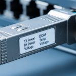
| DOM / diagnostics | Usually supported in modern SFP/SFP+ SR | Usually supported | Not typical; link stats via switch |
Pro Tip: If your switch does DOM polling during link bring-up, a “works most of the time” optic can still cause flap behavior when the switch temporarily rejects an out-of-range diagnostic value. In our case, after we standardized optics with consistent DOM fields and enough temperature margin, CRC bursts dropped and link resets stopped during HVAC ramp.
Implementation steps: how we executed transceiver selection without downtime
We approached transceiver selection like a change-control project, not a parts swap. The goal was to reduce risk while proving optical budget, compatibility, and thermal stability.
Validate link budget with measured fiber loss
Instead of relying on installer “estimates,” we measured end-to-end loss using an OTDR and checked patch panel connector loss. For OM3, even small connector issues can eat into your margin. We used a conservative budget approach: add worst-case connector and splice losses, then verify the optic’s transmit power class and receiver sensitivity from the vendor datasheet.
Confirm switch port behavior and optics compliance
We reviewed the switch vendor’s optics notes and tested a small batch before scaling. Two failure modes were common: optics that didn’t fully support DOM fields the switch expects, and optics that reported values but negotiated at a less stable operating point. We specifically watched for link up/down events and CRC increments during temperature changes.
Choose temperature-rated modules for cabinet reality
Many “standard” optics are rated for normal data center conditions, but IoT cabinets can run hot. We selected modules rated for higher operating temperatures where possible, including examples like FS.com SFP-10GSR-85 class optics and equivalent 85 C rated options, to avoid “works until it gets warm” behavior.

Roll out in pairs and compare telemetry
We swapped optics in pairs within each cabinet, then compared switch port telemetry: CRC counters, link flaps, and error-second rates. After each swap, we ran a controlled thermal cycling window to reproduce the morning issue. This let us confirm that the new transceivers were stable across the same temperature ramp that caused the original flaps.
Measured results: what changed after the transceiver selection rewrite
After replacing the optics in the two problem cabinets, the results were immediate and measurable. We tracked port events and error statistics for two weeks before and after the change window.
- Link flaps: from ~18 per week down to 0 to 1 per week (mostly unrelated maintenance events).
- CRC errors: reduced by over 95% during the HVAC ramp period.
- Error-second spikes: eliminated on the affected uplinks.
- Operational overhead: field tech time spent on “reseat and pray” dropped; we replaced optics plus validated fiber loss instead.

Lessons learned we now bake into selection
The biggest lesson was that transceiver selection is not just about meeting the nominal reach. It is about matching the real link budget and the real switch behavior under diagnostics and temperature drift. We also learned to treat DOM support and operating temperature as first-class requirements for IoT edge gear.
Selection criteria checklist engineers use (ordered)
If you want a repeatable transceiver selection workflow, use this ordered checklist:
- Distance and fiber type: confirm OM3/OM4/OS2, then measure actual loss (OTDR if possible).
- Data rate and standard: ensure it matches the interface (for example 10GBASE-SR over SFP+).
- Budget and margin: validate optical power class and receiver sensitivity against measured losses.
- Switch compatibility: verify vendor port support and optics compliance notes; test small batch first.
- DOM and diagnostics: decide whether you need DOM polling and thresholds for monitoring.
- Operating temperature: match cabinet internal temps; prefer modules with higher temperature ratings when heat is real.
- Connector quality and polarity: confirm LC duplex polarity and patch panel cleanliness.
- Vendor lock-in risk: balance OEM optics vs third-party; plan spares and validate cross-compatibility.
Common pitfalls and troubleshooting tips (root cause + fix)
Here are the top failure modes we see in the field when transceiver selection goes slightly wrong.
Pitfall 1: “Reach should be fine” but connector loss kills margin
Root cause: installers underestimate patch panel loss, dirty connectors, or aging on reused fiber. Even if the optic is rated for the distance, the link budget may be too tight. Solution: measure with OTDR or at least clean and verify with a loss meter; add margin by choosing optics with stronger power class or shorter effective runs.
Pitfall 2: DOM mismatch triggers unstable behavior
Root cause: a module may physically transmit/receive but report diagnostics fields that the switch treats as out-of-spec, causing periodic resets or error bursts. Solution: use optics explicitly supported by the switch vendor or validated with the switch model; confirm DOM readings are stable in telemetry.
Pitfall 3: Temperature-induced drift creates “morning failures”
Root cause: the module’s operating temperature range is narrower than the cabinet environment, or the optic’s power drift pushes the receiver near sensitivity. Solution: select higher temperature rated optics (for example 85 C class where applicable), improve cabinet airflow, and verify stability during thermal cycling.
Pitfall 4: Wrong polarity or swapped fibers after maintenance
Root cause: LC duplex polarity swaps are common when patch panels are reworked; SR optics are sensitive to TX/RX pairing. Solution: follow consistent polarity labeling, verify with a fiber continuity check, and visually confirm patch mapping before reseating.
Cost and ROI note: OEM vs third-party optics
Pricing varies by vendor and temperature grade, but a realistic range for 10G SR optics is often $40 to $120 per module for third-party, and $80 to $200+ for OEM-branded optics depending on channel and rating. TCO matters more than unit price: higher failure rates, repeated truck rolls, and downtime usually dwarf the optics savings.
In our case, the ROI was straightforward. We reduced recurring maintenance time by standardizing on compatible optics with adequate temperature margin, which prevented repeated “re-seat” interventions and reduced error-driven performance issues. The spend increased slightly on the optics line item, but the operational savings from fewer outages and less troubleshooting paid back quickly.
FAQ: transceiver selection for IoT networks
Which transceiver type is best for IoT edge to aggregation links?
Most IoT edge designs use fiber for EMI immunity and stability, so SFP+/SFP 10GBASE-SR over OM3/OM4 is common for short-to-medium distances. If you have long runs or single-mode infrastructure, 10GBASE-LR can be the better fit.
How do I choose between OEM and third-party transceivers?
OEM optics reduce compatibility risk, especially for switches with strict compliance behavior and DOM expectations. Third-party optics can be fine if you validate with your exact switch model and monitor DOM and link stability during temperature swings.
Do I really need DOM support for IoT monitoring?
If your operations team wants early warning on optical power drift or rising error counts, DOM helps you catch problems before they become outages. Even if DOM is optional, having it often improves troubleshooting because you can correlate errors with diagnostic trends.
What temperature rating should I plan for in cabinet deployments?
Base it on worst-case cabinet internal temperature, not just room ambient. If your environment can reach 55 C or higher, plan for optics with enough headroom, like modules rated for 85 C class operation when available.
Why do link flaps happen even when the optic is “supported”?
Supported optics can still flap if the link budget is too tight, connector loss is higher than expected, or polarity is wrong after maintenance. Also, some switches react poorly to unstable DOM telemetry, so validate diagnostics behavior, not only link state.
What should I test before rolling transceiver selection changes site-wide?
Test a small batch with the same fiber runs and watch CRC, link up/down events, and DOM readings during a temperature ramp. If you can, run a short traffic soak and confirm error counters remain flat over the same window that previously caused failures.
If you’re refining your transceiver selection for IoT, start with measured loss and real temperature headroom, then validate switch compatibility and DOM behavior. Next, compare your current optics and fiber plan using fiber transceiver compatibility checklist.
Author bio: I’ve deployed and troubleshot SFP/SFP+ and QSFP optics in mixed IoT edge environments, focusing on link budget math, DOM telemetry, and field stability testing. I help teams turn “it should work” optics choices into measurable reliability improvements.