Teams buy 400G optics under pressure: ports are scarce, outages are expensive, and budgets are finite. This guide helps finance and network engineering teams model transceiver investments with field-ready assumptions—so the spreadsheet survives the rack. You will get a technical ROI lens, a compatibility checklist, and troubleshooting patterns that prevent silent performance loss. Update date: 2026-05-01.
Why 400G transceiver investments break ROI models in the real world
In 3-tier data centers, 400G transceivers often sit at leaf-spine boundaries where traffic is bursty and failure costs are measurable. A typical ROI model that only multiplies unit price by port count misses the hidden drivers: power draw per port, spares and lead times, electrical/optical compatibility, and returns due to vendor optics rules. IEEE 802.3 defines the Ethernet physical layer behavior, but vendor ecosystems define what will actually link up on first boot. For authoritative baseline specs, review [Source: IEEE 802.3 Standard].
Quick ROI frame you can populate today
Use a two-layer model: (1) cost of ownership over a 3 to 5 year horizon, and (2) cost of risk from downtime. Assign dollars to each: optics purchase price, installation labor, power (kWh), failure-driven truck rolls, and warranty/advance replacement strategy. Then tie performance to operational outcomes: error counters, link flaps, and thermal derating events that reduce usable lifetime.
Pro Tip: In many deployments, the biggest “ROI leak” is not the transceiver price; it is the mismatch between optics DOM thresholds and the switch vendor’s optics qualification profile. Engineers see this as intermittent link resets under higher ambient temperatures, which quietly inflate spares consumption and change-control cycles.

400G optics specs that matter for ROI math
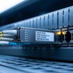
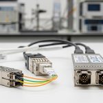
For ROI modeling, specs are not trivia; they determine reach, power, thermal margin, and compatibility. In practice, 400G is commonly delivered via QSFP-DD with optical interfaces like FR4 (multi-lane) or SR4 (short reach) depending on fiber plant. Your model should track wavelength, connector style, reach, and operating temperature, because those drive both capex and the probability of costly field failures. Vendor datasheets and switch vendor optics guidance are the source of truth for deployment limits. See example transceiver datasheets such as Finisar/Supplier listings and vendor documentation for exact power and temperature ratings. [Source: Finisar product resources]
| Parameter | Example 400G Type | Typical Values to Model | Why it affects ROI |
|---|---|---|---|
| Form factor | QSFP-DD | Hot-pluggable, switch-port dependent | Determines switch compatibility and lane mapping |
| Optical reach | FR4 or SR4 | SR4 typically up to ~100 m class; FR4 ~2 km class (varies by vendor) | Impacts whether you need mid-span gear or new fiber runs |
| Wavelength | Multi-wavelength (e.g., 4-lane) | Fiber-plant dependent; often ITU grid for FR4 | Impacts dispersion tolerance and link budget |
| Connector | LC | LC duplex or MPO depending on variant | Drives patch panel cost and installation time |
| Data rate | 400G Ethernet | 400G line rate, Ethernet OTN/PCS dependent | Determines power and DSP complexity |
| Power (per transceiver) | 400G QSFP-DD optical | Varies by type; model using datasheet typical/max | kWh cost and thermal headroom |
| Operating temperature | Commercial/industrial | Often around 0 C to 70 C for many optics | Thermal derating increases failure probability |
| DOM support | Digital Optical Monitoring | Tx/Rx power, bias, temperature, alarms | Enables proactive replacement and reduces downtime |
Deployment scenario: modeling ROI in a leaf-spine fabric
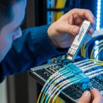
Consider a leaf-spine data center with 48-port 400G uplinks per leaf across 10 leaves, totaling 480 active 400G links. The engineering team plans to use QSFP-DD optics with FR4 to reach 1.8 km between racks, avoiding a fiber trench redesign. Each link needs a pair of transceivers, so you model 960 transceivers as baseline plus a 3% spares buffer for planned swaps. If each transceiver costs $1,200 to $2,000 for OEM or vetted third-party (varies by volume and contract), capex alone ranges roughly from $1.4M to $2.0M before installation and testing labor.
Now layer in power: if typical average draw is, say, 10 W per transceiver (use your datasheet typical), energy over 3 years becomes kWh times your $/kWh rate. Add failure cost: assume a low-but-not-zero probability of a DOA or early failure that triggers a truck roll and a staged swap window. The ROI model improves dramatically when you include operational downtime minutes multiplied by business impact, rather than treating failures as “rare noise.”

Selection checklist for transceiver investments (engineer and finance aligned)
Use this ordered list during procurement and pre-acceptance testing. It reduces both cost overruns and late-stage compatibility churn.
- Distance vs reach class: verify fiber plant loss and connector polish quality against vendor reach claims; do not rely on “max reach” marketing.
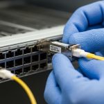
- Switch compatibility: confirm the switch model supports the exact transceiver SKU and lane mapping; check vendor optics compatibility lists.
- DOM and monitoring: ensure the switch can read alarms and thresholds; confirm telemetry fields integrate with your NMS/telemetry pipeline.
- Operating temperature: match transceiver temperature rating to measured inlet air temps at the port side; budget margin for seasonal drift.
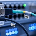
- Connector and patch strategy: LC vs MPO affects patch panel cost, cleaning procedures, and installation time.
- Vendor lock-in risk: evaluate OEM-only support vs vetted third-party; model return rates and warranty process friction.
- Spare strategy and lead time: include realistic replacement lead times and stocking policy; failure without spares is downtime.
Verification steps before you sign
- Run a staged burn-in with link-level monitoring (CRC/FEC counters where applicable) and DOM threshold logging.
- Validate under worst-case thermal conditions by replicating inlet temperatures from the highest-density aisle.
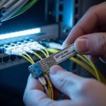
- Confirm optics cleaning workflow: inspect end faces, use lint-free wipes, and verify MPO polarity where relevant.
Common pitfalls and troubleshooting patterns
Even seasoned teams stumble when the optics ecosystem is treated like commodity hardware. Below are failure modes that directly distort ROI by driving rework, RMA cycles, and unplanned downtime.
-
Pitfall 1: “It links but it flaps.”
Root cause: marginal optical power or connector contamination causes intermittent receiver sensitivity failures.
Solution: clean and re-terminate, verify fiber loss with OTDR, and compare Rx power DOM readings to vendor alarm thresholds. -
Pitfall 2: “Only certain ports fail.”
Root cause: switch backplane/ASIC port qualification differences or lane mapping assumptions mismatch with the optics vendor’s implementation.
Solution: test the optics across multiple ports, confirm the switch supports that exact transceiver model, and align firmware to the vendor’s recommended release. -
Pitfall 3: “RMA rate spikes after summer.”
Root cause: transceivers operating near or beyond the intended thermal envelope, triggering performance degradation long before hard failure.
Solution: instrument inlet temperatures, enforce thermal mitigation (fan curves, baffles), and select optics with sufficient temperature margin. -
Pitfall 4: “DOM telemetry is missing or misleading.”
Root cause: unsupported DOM fields or telemetry polling intervals causing gaps in monitoring, delaying detection of drift.
Solution: validate telemetry ingestion in staging and confirm alarm mapping in your NMS.

Cost and ROI note: OEM vs third-party transceiver investments
Typical enterprise pricing for 400G QSFP-DD optics ranges broadly: $1,200 to $2,000 per transceiver for many common reach classes, with OEM often higher and third-party sometimes lower but with higher integration variance. TCO should include: power cost (kWh), expected failure/return handling, and labor for cleaning and swaps. If your spare policy is aggressive, the ROI may improve in outage-sensitive sites, but it increases inventory carrying cost