If your stack uplinks are flakey, the whole chassis group behaves like a single point of failure. This article helps network engineers and data center field techs pick the right switch stack uplink SFP for VSS and IRF-style stacking, with real-world compatibility checks for optics, DOM behavior, and environmental limits. You will also get troubleshooting patterns from deployments where a single transceiver mismatch caused intermittent stack member drops.
VSS vs IRF stacking: what changes for uplink SFPs
In VSS and IRF designs, the “stack” is effectively a logical control plane link between switch members. That makes the stack uplink SFP behave differently from ordinary server access optics: link stability, timing, and vendor-specific electrical requirements matter. In practice, you should treat stack uplinks as a high-availability subsystem, not a generic fiber hop.
VSS-style designs typically rely on a defined interconnect architecture with strict optics support lists and timing expectations; IRF-style designs similarly depend on approved transceivers and consistent signal parameters across members. If you mix vendor optics, even at the same data rate and wavelength, you may see DOM warnings, link flaps, or stack formation failures. For standards grounding, IEEE Ethernet PHY behavior is governed by IEEE 802.3, while transceiver control and diagnostics follow vendor implementations. Source: IEEE 802.3
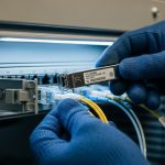
Pro Tip: In stack deployments, the “works in a test bench” optics can still fail during live upgrades because stack formation is sensitive to transient link events. Always validate with the same firmware level and confirm the vendor’s optics compatibility list before swapping in the field.

Spec comparison: common stack uplink SFP options and limits
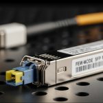
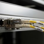
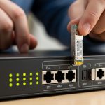
Most stack uplinks in modern enterprise and campus designs use SFP+ or SFP28-class optics, even when the stacking feature is described as “SFP.” The module must match the switch port electrical interface, supported data rate, fiber type, and reach class. Below is a practical comparison of typical choices engineers see when they map stacking requirements to optical budgets.
| Module type | Typical wavelength | Reach (typical) | Connector | Data rate | DOM support | Operating temp |
|---|---|---|---|---|---|---|
| SFP-10G-SR (multimode) | 850 nm | ~300 m (OM3), ~400 m (OM4) | LC | 10G | Yes (vendor-specific) | 0 to 70 C or wider |
| SFP-10G-LR (single-mode) | 1310 nm | ~10 km | LC | 10G | Yes (vendor-specific) | -5 to 70 C |
| SFP+ or SFP28 stack uplink (SR/active) | 850 nm or vendor-specified | Short-reach to rack-to-rack | LC (often) | 10G-25G (depends) | Often required | 0 to 70 C (check datasheet) |
When choosing for VSS or IRF stacks, prioritize the exact transceiver family your switch OS expects. Examples you may encounter in the field include Cisco optics like Cisco SFP-10G-SR and third-party models sold as compatible, such as Finisar FTLX8571D3BCL or FS.com variants like FS.com SFP-10GSR-85. Always confirm the vendor’s compatibility note because “same reach class” does not guarantee identical control-plane behavior.

Compatibility and selection criteria checklist for stack uplinks
Engineers typically decide quickly, but stack uplinks reward disciplined verification. Use this ordered checklist before ordering optics or swapping modules during a maintenance window.
- Distance and fiber type: confirm OM3/OM4 for SR links; confirm single-mode OS2 for LR; measure with an OTDR when possible.
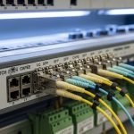
- Switch port and stacking mode: verify the port is actually designated for stack uplink in your VSS/IRF configuration guide.
- Data rate and optics class: match SFP vs SFP+ vs SFP28; confirm whether the stack link is configured for 10G or 25G.
- Compatibility list: check the exact model and vendor part number supported by your switch generation and firmware.
- DOM and threshold behavior: ensure the switch reads DOM without raising “unsupported diagnostics” alarms; confirm RX power thresholds are realistic.
- Operating temperature: validate module spec versus the rack’s thermal profile; stacks often run warmer due to link utilization.
- Vendor lock-in risk: evaluate third-party optics only when the switch vendor explicitly supports them or when your field testing shows stable stack formation.
For field validation, plan a short acceptance test: bring up the stack, verify member state stability for at least 30 to 60 minutes, then confirm no DOM-related events in syslog. If you can, include a controlled reload of one member to observe stack reformation behavior.

Cost and ROI: OEM vs third-party optics in stack deployments
OEM optics often cost more upfront, but they can reduce operational risk when stack behavior is sensitive to transceiver control interactions. In many deployments, OEM SFP+ optics land in a range of roughly $80 to $250 per module depending on vendor and reach. Third-party compatible optics may be $30 to $120, but the TCO changes when you factor failure rates, time to troubleshoot stack formation, and the cost of outages during maintenance.
For ROI, treat stack uplink optics like a reliability component: a cheaper module that triggers intermittent stack flaps can consume more labor hours than the price difference. Also consider spares strategy—buy at least a minimal set of verified spares matching the current firmware and part numbers, since swapping unknown optics later is slower during incidents.
Common mistakes and troubleshooting tips
These are frequent failure modes I have seen when engineers swap optics for VSS or IRF stacks.
- Mistake: mixing optics vendors or part families
Root cause: DOM implementation and laser/RX thresholds differ, leading to stack link flaps or “stack not formed.”
Fix: use the switch vendor’s approved optics list; standardize on one part family across all stack members. - Mistake: using SR multimode optics on a link with the wrong fiber type
Root cause: OM mismatch and higher attenuation cause low RX power; stack links may drop under load.
Fix: verify fiber type (OM3 vs OM4) and clean connectors; re-measure with a light meter or OTDR. - Mistake: ignoring temperature and airflow differences between data and stack ports
Root cause: stack links are often bidirectionally active; modules can exceed spec in hot aisles or poorly ventilated racks.
Fix: check rack inlet temperatures; improve airflow; confirm module temperature range against datasheet. - Mistake: not seating or cleaning LC connectors
Root cause: micro-scratches or dust create intermittent RX errors that look like stack instability.
Fix: follow cleaning best practices (lint-free wipes and approved cleaners), then reseat and retest.
Decision matrix: pick the right switch stack uplink SFP
Use this quick matrix to decide between SR multimode, LR single-mode, and vendor-verified stack optics.
| Scenario | Best fit | Why | Key risk |
|---|---|---|---|
| Rack-to-rack within same room, known OM4 | 10G SR (850 nm) or approved stack SR SFP+ | Meets reach with margin and simpler fiber | Connector cleanliness and OM mismatch |
| Inter-room or longer fiber runs | 10G LR (1310 nm) on OS2 | Single-mode budget supports longer reach | Wrong fiber type or excessive splice loss |
| High-availability stack where every minute matters | Vendor-approved OEM or explicitly validated compatible stack optics | Predictable DOM and stack formation behavior | Higher cost, but lower operational risk |
| Budget-constrained expansion with proven lab test | Third-party optics only after compatibility testing | Lower purchase cost | Unexpected DOM/threshold differences |
Which Option Should You Choose?
If you are deploying a new VSS or IRF stack today, choose the optics that match your switch vendor’s approved stack uplink list first, then pick SR vs LR based on fiber type and measured loss. If you already run stable stacking with a known transceiver family, keep that consistency across all members and spares to avoid revalidation during outages.
For greenfield builds with limited time, start with vendor-verified OEM optics; for controlled