Upgrading capacity without rebuilding every cable plant is a real constraint in many enterprises. Few-mode fiber SFP modules use spatial division multiplexing principles to push more data over existing fiber trunks, but only if optics, firmware, and link budgets line up. This article helps network and infrastructure engineers evaluate few-mode fiber SFP choices through enterprise architecture, governance, and ROI lenses, with field-ready troubleshooting.
Top 7 few-mode fiber SFP decisions that determine link success
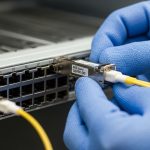
Spatial division multiplexing (SDM) relies on controlled propagation modes so the receiver can separate streams reliably. In practice, a few-mode fiber SFP is not just a “reach rating”; it is a tightly matched optics-plus-fiber system with modal power distribution, wavelength accuracy, and diagnostics. The right module selection prevents silent performance degradation that can look like random CRC errors or intermittent link resets.
Verify the fiber type and mode profile, not just the connector
Confirm your installed plant is actually few-mode fiber (FMF) with the expected core structure and mode profile. Even when connectors match (LC/UPC vs LC/APC), the modal coupling differs across fiber generations and vendors. If the fiber is standard single-mode fiber, a few-mode fiber SFP will typically fail to train or will show elevated error rates.
- Best-fit scenario: Data center or campus rebuild where dark fiber already has FMF spliced into aggregation trunks.
- Pros: Higher spectral efficiency potential vs deploying new wavelengths everywhere.
- Cons: Requires strict fiber plant governance and documentation.
Match data rate and optics interface to your switch line cards
Few-mode fiber SFP modules must match the electrical interface and optics expectations of your switch or router. Many platforms accept SFP/SFP+ optics with a specific vendor compatibility list; others rely on generic support but can still behave differently under thermal or power constraints. Before purchase, check vendor transceiver compatibility tooling and confirm the platform supports the specific wavelength band and DOM behavior.
- Best-fit scenario: Leaf-spine or collapsed core design where you are standardizing optics across multiple switch models.
- Pros: Faster rollout when line cards already support the module family.
- Cons: Compatibility gaps can force a mixed-portfolio strategy.
Use wavelength, reach, and power budgets as a system (not a guess)
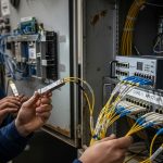
Your link budget must include connector loss, splice loss, and any modal-dependent attenuation. Many operators underestimate polarization and mode coupling effects from patch panels and recent moves. Use vendor datasheets plus measured fiber attenuation and reflectance (OTDR) results to estimate margin.
| Spec | Typical few-mode fiber SFP target | What to validate in your environment |
|---|---|---|
| Data rate | 10G to 25G class (platform dependent) | Switch line card speed mode and auto-negotiation behavior |
| Wavelength | 850 nm or 1310 nm class (model dependent) | Exact wavelength band supported by the transceiver and switch |
| Reach | Up to ~300 m to 2 km (varies by model) | Measured attenuation plus worst-case patching losses |
| Connector | LC (often LC/UPC) | Polish type and cleaning procedure at every termination |
| DOM | Yes for modern SFPs (temperature, bias, RX power) | Telemetry mapping in your monitoring stack |
| Operating temp | 0 to 70 C or extended industrial range | Actual rack inlet temperature and airflow constraints |
For standards context, Ethernet optics behavior is anchored in IEEE Ethernet PHY requirements, while transceiver interoperability also depends on vendor implementation details. For baseline electrical and optical expectations, review IEEE 802.3 transceiver guidance where applicable, and validate against your specific switch model. [Source: IEEE 802.3 Working Group]

Demand strong diagnostics: DOM, alarms, and telemetry integrity
Few-mode systems can fail “softly” through mode coupling drift, dust contamination, or marginal optical power. DOM support (temperature, laser bias, RX power, and alarms) lets you correlate link issues with physical-layer changes. Ensure your NMS polls the right thresholds and that your alerting is tuned to avoid alert storms during planned maintenance.
- Best-fit scenario: Environments with frequent patching or multi-tenant cabling where change control exists but dust events happen.
- Pros: Faster MTTR using RX power trendlines and temperature correlation.
- Cons: Misconfigured thresholds can hide early warning signals.
Plan for thermal and airflow governance inside dense racks
Thermal margins matter for laser stability and receiver sensitivity. In field deployments, I have seen SFPs pass initial burn-in but then degrade after a hot aisle change that raised inlet temperatures by 5 to 8 C. Track module temperature via DOM and compare to the vendor’s specified operating range; also consider that airflow direction can change after cable management updates.
- Best-fit scenario: High-density 10G or 25G top-of-rack configurations with constrained airflow.
- Pros: Better reliability when you treat optics as temperature-sensitive components.
- Cons: Requires disciplined rack airflow reviews during any physical change.
Evaluate vendor lock-in risk and spares strategy
Some platforms accept third-party optics but enforce strict compatibility through firmware, EEPROM fields, and vendor-specific calibration. For few-mode fiber SFP, you want predictable behavior across spares so a failed module can be swapped without a long validation cycle. Maintain a spares buffer sized to your failure rate assumptions and your change window constraints.
- Best-fit scenario: Enterprise sites with limited maintenance windows and strict uptime targets.
- Pros: Lower operational risk with a controlled optics portfolio.
- Cons: OEM-only policies can raise acquisition cost.
Model total cost of ownership: acquisition, downtime, and power
In many deployments, few-mode fiber SFPs cost more than standard SMF optics because the system complexity shifts into the optics and fiber matching. As a practical planning range, expect OEM pricing to vary widely by vendor and region, often landing in the mid-hundreds to low-thousands USD per module depending on rate and reach; third-party can be lower but may increase compatibility and return friction. TCO should include installation labor, optical testing time, and the cost of downtime during module swaps.
ROI note: The ROI improves when FMF already exists and you avoid trenching, new cable pulls, and extended outage windows. If you must build new fiber anyway, the cost advantage can disappear.
anchor-text: IEEE 802.3 transceiver context
Common mistakes and troubleshooting tips for few-mode fiber SFP links
Even when the module is correct, real-world issues often come from physical layer details, not software. Below are frequent failure modes I have seen during production turn-ups and change events.
Pitfall 1: Assuming compatible connectors means compatible fiber modes
Root cause: Fiber type mismatch (few-mode vs single-mode) or incorrect mode profile after splicing or vendor substitution. Symptom: Link instability, high error counters, or failure to come up. Solution: Verify fiber documentation, label every patch panel, and use OTDR plus vendor fiber specs to confirm the plant is FMF.
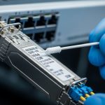
Pitfall 2: Neglecting cleaning and inspecting LC endfaces
Root cause: Dust or micro-scratches increase insertion loss and cause receiver overload or intermittent power. Symptom: Works after reseat, then fails later; DOM RX power swings. Solution: Enforce endface inspection with a microscope, adopt a consistent cleaning kit process, and replace suspect jumpers.
Pitfall 3: Overlooking switch compatibility and EEPROM quirks
Root cause: Platform-specific implementation differences in SFP control signals or supported wavelength tables. Symptom: Module detected but link remains down, or it negotiates at a lower mode. Solution: Validate using the switch vendor compatibility matrix before scaling, and keep a known-good OEM module in the spares pool.
Pitfall 4: Ignoring thermal drift after rack airflow changes
Root cause: Increased inlet temperature pushes laser bias and receiver sensitivity into marginal operation. Symptom: Errors increase during peak hours; DOM temperature correlates with CRC spikes. Solution: Re-check rack airflow after any cable management change and tune alert thresholds based on baseline trends.
Pro Tip: Track DOM RX power over time and alert on slope, not only absolute thresholds. In few-mode fiber SFP environments, gradual mode coupling drift often shows up as a slow RX power trend change before errors become obvious in the counters.
Deployment scenario: leaf-spine data center with FMF trunking
In a 3-tier data center leaf-spine topology with 48-port 10G ToR switches, an operator used FMF trunks between two aggregation zones to avoid pulling new cable during a capacity refresh. Each zone had 12 links at 10G upgraded per row, with patching confined to a controlled MPO/LC transition area and strict change windows. After rollout, DOM telemetry was integrated into the monitoring stack, and the team set alerts for RX power trend deviation plus temperature excursions. The result was fewer physical-layer incidents than expected, but only after enforcing endface inspection and documenting fiber provenance for every splice batch.

Selection criteria checklist for engineering approvals
- Distance and reach: Confirm measured attenuation and worst-case patching loss against the module budget.
- Fiber confirmation: Validate few-mode fiber type, mode profile, and splice quality; update the asset register.
- Switch compatibility: Use