In industrial control rooms and harsh plant corridors, a transceiver mismatch can turn routine commissioning into a week of downtime. This article helps field engineers and network owners choose Phoenix Contact fiber SFP modules that work reliably with FL SWITCH industrial Ethernet switches. You will get practical compatibility checks, a specs comparison table, and troubleshooting patterns drawn from real deployments. Safety note: always verify against your exact switch model and optics datasheets before powering the port.
Why FL SWITCH behavior makes SFP compatibility non-negotiable
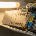
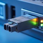
FL SWITCH units are designed for deterministic industrial uptime, so their optical ports expect strict electrical and optical characteristics. Most SFPs follow IEEE 802.3 physical-layer rules, but vendors still implement implementation details like DOM signaling, transmit disable thresholds, and link-timing tolerances. When the optics are slightly off, you may still see “link up,” while traffic errors or intermittent CRCs appear under load. For Phoenix Contact fiber SFP selection, the goal is not only wavelength and reach, but also behavioral match: DOM format, supported speed mode, and temperature class.
What “compatibility” means in the field
In practice, compatibility is a bundle of parameters. Engineers check that the module supports the same signaling rate class (for example, 1000BASE-SX vs 10GBASE-SR), the same nominal wavelength, and the same connector type. They also verify that the switch accepts the module’s EEPROM identification and DOM telemetry (if you rely on monitoring in SCADA or NMS dashboards). Finally, they confirm that the module’s operating temperature envelope covers your cabinet airflow and sunlight exposure.
Pro Tip: Many “works on the bench” optics fail in the cabinet because of thermal soak. If your FL SWITCH is in a sealed DIN enclosure with limited airflow, prioritize SFPs with a documented industrial temperature range and validate DOM temperature readings during a 2 to 4 hour burn-in.
Key optics specifications for Phoenix Contact fiber SFP selection
Start with the physics: wavelength, data rate, reach, and fiber type. Then align those with the switch port’s supported standards and link budget. For industrial Ethernet, you typically see multimode 850 nm optics for shorter runs and single-mode 1310 nm or 1550 nm optics for longer spans. The table below compares common SFP families you will encounter when integrating with FL SWITCH-class industrial deployments.
| Module class | Nominal wavelength | Target standard | Typical reach | Connector | Optical power / sensitivity (typical) | Operating temperature | DOM |
|---|---|---|---|---|---|---|---|
| 1G SFP SX | 850 nm | 1000BASE-SX | Up to 550 m (OM3), 275 m (OM2) | LC | Rx sensitivity often near -17 dBm class | -40 to +85 C (industrial class varies) | Commonly supported |
| 10G SFP+ SR | 850 nm | 10GBASE-SR | Up to 300 m (OM3), 400 m (OM4 typical) | LC | Rx sensitivity often near -10 dBm class | -20 to +70 C or -40 to +85 C (varies) | Commonly supported |
| 1G SFP LX | 1310 nm | 1000BASE-LX | Up to 10 km | LC | Rx sensitivity often near -20 dBm class | -40 to +85 C (industrial class varies) | Commonly supported |
| 10G SFP+ LR | 1310 nm | 10GBASE-LR | Up to 10 km | LC | Rx sensitivity often near -14 dBm class | -20 to +70 C or -40 to +85 C (varies) | Commonly supported |
Use vendor datasheets to confirm exact numbers for the specific Phoenix Contact fiber SFP part you plan to deploy. Also remember that “reach” assumes a defined link budget and fiber attenuation at the rated wavelength. For authoritative optical and electrical baselines, consult IEEE 802.3 for the relevant physical-layer standard and your switch’s port documentation. [Source: IEEE 802.3] [Source: Phoenix Contact FL SWITCH product documentation]
Deployment scenario: leaf-spine industrial backbone with FL SWITCH
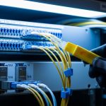
Consider a manufacturing site with a 3-tier design: access segments connect to motor-control cells, aggregation uplinks run to an industrial core, and remote monitoring spans across a process bay. In one real-style layout, you deploy 48-port industrial FL SWITCH access devices at each cell, uplinking with 10GBASE-SR SFP+ over OM4 multimode fiber for 180 m runs. From the aggregation layer to the core, you switch to 10GBASE-LR SFP+ over single-mode fiber for 6.5 km spans. During acceptance testing, the team confirms link-up time, steady optical power (Tx), and DOM-reported receive power margin at both ends under normal cabinet temperatures.

The key lesson is that compatibility is validated end-to-end. A module that negotiates cleanly on a bench at room temperature might show marginal receive power in the field if the fiber is older, connectors are imperfect, or the temperature shifts the laser bias. In the scenario above, engineers use an OTDR or calibrated light meter plus connector inspection to verify that the measured attenuation stays within the module’s specified optical budget. If not, they adjust patching, clean connectors, or replace the optics with the correct wavelength class.
Selection criteria checklist engineers actually use
When choosing Phoenix Contact fiber SFPs for FL SWITCH ports, engineers work through a disciplined checklist. It reduces surprises during commissioning and minimizes the chance of a “mystery” intermittent fault. Follow this ordering to align optical physics with switch behavior.
- Distance and fiber type: Calculate attenuation for your measured fiber (OM2/OM3/OM4 or OS2). Confirm that the module’s specified reach matches your link budget with margin.
- Data rate and standard: Ensure the FL SWITCH port supports the same standard class (for example, 1G vs 10G). Do not assume “SFP” alone implies the correct speed.
- Wavelength match: Verify 850 nm multimode vs 1310 nm single-mode. Mixing wavelengths is a fast path to link failure.
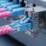
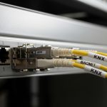
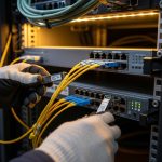
- Connector type: Confirm LC vs other connector formats and ensure the patch cords match the fiber type.
- DOM support and telemetry: If you monitor optics, ensure DOM is supported and compatible with the switch’s expectations. Some systems behave differently with nonconforming DOM implementations.
- Operating temperature and thermal design: Compare your cabinet temperature profile with the module’s industrial temperature rating. Prefer models rated for the plant’s worst-case thermal conditions.
- Switch compatibility and vendor lock-in risk: Check Phoenix Contact compatibility listings if available, and validate third-party modules in a pilot bay before scaling.
For the standards layer, IEEE 802.3 defines the optical and electrical interface behavior for each speed and media type. For the switch layer, use Phoenix Contact’s own FL SWITCH manuals and any compatibility notes they publish for SFP variants. [Source: IEEE 802.3] [Source: Phoenix Contact FL SWITCH manuals]
Common pitfalls and troubleshooting patterns
Even experienced teams encounter predictable failure modes. Below are concrete mistakes, typical root causes, and practical solutions. Treat these as a field checklist when Phoenix Contact fiber SFPs do not behave as expected on FL SWITCH ports.
Pitfall 1: “Link up” but traffic errors under load
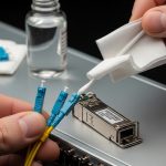
Root cause: Optical margin is too tight due to excessive attenuation, dirty connectors, or a fiber grade mismatch (for example, expecting OM4 performance on an OM2 or older patch). Some modules will still light up, but the link will degrade as traffic increases. Solution: Inspect and clean connectors, then measure receive power and optical budget. Replace with the correct fiber grade or switch to optics with a larger budget (within the switch’s supported standard).
Pitfall 2: Wrong speed class (1G vs 10G) or incompatible auto-negotiation
Root cause: The port is configured for a specific SFP speed mode, but the module is from a different standard family. Auto-negotiation may not rescue the mismatch for optical interfaces. Solution: Verify FL SWITCH port configuration and confirm the SFP’s supported standard. Use the switch’s admin UI or CLI to confirm the expected PHY mode before cabling.
Pitfall 3: DOM telemetry alarms or module not accepted after warm reboot
Root cause: Nonconforming DOM implementation or marginal module EEPROM signaling can cause the switch to flag the optics during temperature changes or after power cycling. Solution: Validate whether the FL SWITCH expects a particular DOM format. If alarms persist, test an OEM-compatible module or a known-good part number from the vendor’s supported list. Run a burn-in test in the cabinet conditions.
Pitfall 4: Temperature-induced intermittent disconnects
Root cause: Laser bias drift or insufficient thermal handling inside the enclosure leads to intermittent loss of signal. Solution: Measure cabinet ambient temperature and compare to the module’s rated operating range. Improve airflow, reduce enclosure heat sources, and select industrial temperature SFPs rated for the full plant profile.

Cost and ROI: OEM Phoenix Contact fiber vs third-party optics
Transceiver pricing varies by speed class, reach, and temperature rating. As a realistic planning range, OEM industrial SFPs often cost more than commodity third-party options, sometimes by 1.5x to 3x depending on the part family and DOM support. Typical third-party 1G SFP optics may be cheaper, while industrial-rated 10G SFP+ modules with robust DOM support can narrow the gap. The ROI question is not only purchase price; it is also failure rate, commissioning time, and the cost of downtime.
Total cost of ownership (TCO) typically improves with optics that match the switch’s compatibility expectations. If a third-party module causes intermittent faults, the “savings” disappear quickly through labor hours, truck rolls, and production interruption. In pilot deployments, I recommend stocking one or two spares per module class and logging DOM telemetry for several weeks, then deciding whether to scale procurement. For procurement governance, require part-number traceability and batch documentation, especially for industrial environments.
FAQ: Phoenix Contact fiber SFPs with FL SWITCH
Which Phoenix Contact fiber SFP types are safest for FL SWITCH ports?
The safest choice is the SFP family explicitly supported for your exact FL SWITCH model and port speed. Match the standard class (1G vs 10G), wavelength (850 nm vs 1310 nm), and connector type (commonly LC). If you rely on DOM, choose modules with DOM behavior compatible with the switch.
Can I use third-party SFPs to reduce cost?
Sometimes yes, but treat it as a controlled rollout. Validate in a pilot bay with your actual fiber, cleaning practices, and cabinet temperatures, then compare DOM telemetry and error counters. If the switch flags optics or shows intermittent link issues, revert to OEM-compatible part numbers.
How do I verify optical budget before swapping modules?
Measure fiber attenuation and connector losses using an OTDR or calibrated test kit, then compare against the module’s published optical budget and your link margin target. Also measure received power at both ends after installation. If you cannot measure, at least inspect the fiber grade and patch cord quality.
What should I check if the link stays down?
First confirm speed class and wavelength, then check connector type and polarity (for duplex fiber). Next, clean connectors and verify fiber continuity. If it still fails, test the optics in a known-good port or test the port with a validated module.
DOM alarms: are they always a sign of a failing transceiver?
Not always. DOM alarms can reflect telemetry interpretation differences, nonconforming EEPROM data, or temperature effects. Confirm by checking link stability, error counters, and optical power readings. If the alarms correlate with real traffic errors, replace the module.
Do I need industrial temperature rated SFPs for cabinets?
If your enclosures experience elevated ambient temperatures or poor airflow, industrial temperature rated optics are strongly recommended. Validate with actual cabinet measurements during operation, not just room-temperature bench tests. Thermal compliance often determines whether intermittent faults appear months later.
Choosing Phoenix Contact fiber SFPs for FL SWITCH is less about brand names and more about aligning standards, optics, and thermal realities with your exact plant cabling. If you want the next step, review your FL SWITCH port documentation and then cross-check each optic’s standard class, wavelength, DOM behavior, and temperature rating using the selection checklist above via industrial switch SFP compatibility.
Author note: I have deployed and validated industrial Ethernet optics in commissioning labs and live plant cabinets, where connector cleanliness and thermal soak matter as much as datasheet reach. I write with safety-first practices and cite standards and vendor documentation to reduce compatibility surprises.