When a high-speed uplink suddenly goes down, the outage is rarely “mysterious” — it is usually measurable. This article helps network engineers and field technicians perform optical troubleshooting end-to-end, from transceiver DOM readings and optical budgets to fiber polarity and connector hygiene. You will get a step-by-step implementation workflow, common failure modes, and selection criteria for the right SFP/SFP+/QSFP optics and replacement parts.
Prerequisites for optical troubleshooting in production networks
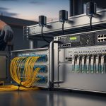
Before you touch anything, confirm you can safely access the affected ports and optics. Gather the switch model, transceiver part numbers, and the intended standard (for example, IEEE 802.3ae for 10G Ethernet, IEEE 802.3ba for 40/100G). You also need a known-good patch cord set and a fiber inspection method (visual scope or microscope).
Operationally, plan for link flap risk: many platforms will hold ports in a disabled state if repeated DOM or signal-loss faults occur. If you have redundancy (dual-homed uplinks), isolate the failure to one path while keeping traffic on the other. Where possible, document current DOM alarms and interface counters before making changes.
What to collect before starting
- Interface identifiers: switch port numbers and peer port IDs.
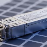
- Optics details: vendor and model (example: Cisco SFP-10G-SR, Finisar FTLX8571D3BCL, FS.com SFP-10GSR-85).
- DOM readings: RX power, TX bias current, temperature, and “LOS” or “LOF” indicators.
- Fiber facts: link type (OM3/OM4/OS2), length, and patch panel mapping.

Step-by-step optical troubleshooting workflow for link failures
This workflow assumes Ethernet transceivers and duplex fiber cabling. It is designed to narrow the fault from “optics vs fiber vs configuration” quickly using measurable signals and repeatable checks.
Confirm the failure scope and counters
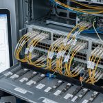
Check whether the failure is local (one port) or systemic (multiple ports). On the switch, capture interface status and error counters, including CRC/FCS errors, input errors, and link state. If the platform provides a transceiver alarm log, export it so you can correlate events with the time the link dropped.
Expected outcome: You can classify the incident as “no light received” (often LOS), “low received power,” or “light present but frames failing.”
Read DOM values and interpret LOS/LOF
Use DOM telemetry to determine whether the transmitter is alive and whether the receiver is seeing power. For typical short-reach optics, RX power should be within the module’s specified operating range; if RX is near sensitivity limits, the link may flap under temperature variation. If LOS is asserted, suspect fiber break, wrong polarity, or disconnected patch cords.
Expected outcome: You determine whether the problem is “no optical signal,” “weak optical signal,” or “optical signal present with data errors.”
Validate distance, fiber type, and optical budget
Compare the planned link length and patch loss to the optics’ supported reach. For example, 10G SR modules are specified for multimode distances and assume typical cabling loss; exceeding the budget can still pass at room temperature but fail in colder or hotter conditions. Ensure you are using the correct fiber category (OM3 vs OM4) and that patch panels are not miswired.
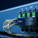
Inspect and clean connectors, then verify polarity
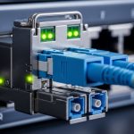
Most “intermittent” optical troubleshooting cases trace back to connector contamination or polarity reversal. Clean LC/SC endfaces using lint-free wipes and approved cleaning tools; then re-seat the optics and patch cords. Verify duplex polarity by mapping Tx on one side to Rx on the other, consistent with the transceiver label and patch panel keying.
Expected outcome: LOS clears and RX power returns to a stable range.
Reseat, replace optics, and retest with known-good parts
Reseat transceivers to restore proper alignment, then test with a known-good module of the same type and wavelength. If the fault moves with the module, replace it; if the fault stays with the port/cabling, focus on fiber and connectors. Keep spare optics matched by standard and speed (for example, 10G SR vs 1G SX are not interchangeable).
Expected outcome: The link comes up and remains stable under normal temperature and traffic load.
Key optics specs engineers compare during optical troubleshooting
Different optics have different wavelengths, reach, and power characteristics, so “it fits the cage” is not enough. Use the table below as a quick reference while you verify module type and compatibility with the switch vendor’s supported transceiver list.
| Module example | Data rate | Wavelength | Typical reach | Connector | Operating temp | Common failure signal |
|---|---|---|---|---|---|---|
| SFP-10G-SR class (multimode) | 10G | ~850 nm | Up to ~300 m (OM3) / ~400 m (OM4) | LC duplex | ~0 to 70 C (varies by vendor) | LOS asserted or low RX power |
| SFP+/QSFP+ for 1310 nm SM (example class) | 10G or 40G/100G (varies) | ~1310 nm | Up to a few km (varies by design) | LC/APC or UPC (varies) | ~0 to 70 C (varies) | Weak RX due to budget overrun |
| QSFP28 LR4 class (example) | 100G | ~1310 nm (multi-lane) | ~10 km (varies by vendor) | LC duplex | ~0 to 70 C (varies) | Some lanes failing, intermittent FEC errors |

Selection criteria checklist to prevent repeat optical troubleshooting
- Distance vs reach: verify actual measured loss including patch panels and splices.
- Fiber type and wavelength: OM3/OM4 for SR at ~850 nm; OS2 for 1310/1550 nm designs.
- Switch compatibility: confirm the transceiver is supported by the switch OS and hardware revision.
- DOM support and alarm behavior: ensure your platform reads vendor-specific thresholds correctly.
- Operating temperature: match transceiver spec to the enclosure airflow and ambient conditions.
- Vendor lock-in risk: decide between OEM and third-party based on documented compatibility and warranty terms.
Pro Tip: In many field cases, the fastest confirmation is to swap only the transceiver on one side while keeping the fiber path identical. If RX power recovers immediately, the fault is optical; if it does not, connector cleanliness, polarity, or patch mapping is more likely than “bad electronics.”
Common mistakes and troubleshooting tips
Even experienced teams can waste hours when they skip the measurable step. Below are three common failure modes with root causes and practical fixes.
Failure mode 1: Wrong polarity through duplex patching
Root cause: Tx-to-Tx or Rx-to-Rx wiring in the patch panel flips the duplex path. The link may show LOS or remain down entirely.
Solution: verify polarity mapping end-to-end; re-patch so one side’s Tx goes to the other side’s Rx. Re-test DOM RX power after each repatch.
Failure mode 2: Connector contamination after “it was working yesterday”
Root cause: fine dust or micro-scratches increase insertion loss and cause intermittent link drops, especially under vibration or thermal cycling.
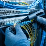
Solution: clean both ends with approved fiber-cleaning procedures, inspect endfaces under magnification, then reseat. Avoid compressed air unless the tool is specifically designed for fiber end cleaning.
Failure mode 3: Exceeding optical budget with extra patching
Root cause: the installed cabling differs from the as-designed length: extra patch cords, additional panels, or unplanned splices increase loss.
Solution: measure or estimate total loss using vendor specs for insertion loss and connector/splice penalties. If near threshold, shorten the path, replace with lower-loss cords, or move to a higher-reach module.
Cost and ROI note for optical troubleshooting replacements
Third-party optics often cost less up front, but total cost depends on failure rate, compatibility issues, and downtime. In typical enterprise deployments, replacement SFP/SFP+ modules may range from roughly $30 to $150 depending on reach and vendor; higher-speed QSFP/QSFP28 can be $200 to $600+. OEM modules may carry higher purchase price but can reduce time spent