In modern optical networking rollouts, the hard part is not “can we do 400G,” it is picking the right transceiver so it matches fiber plant, switch optics, and operational constraints. This buying guide helps network engineers and procurement teams compare 400G QSFP-DD and OSFP options across SR4, DR4, and FR4, with concrete compatibility and troubleshooting details. You will leave with a practical decision checklist and a cost-aware selection matrix you can apply to leaf-spine, aggregation, and metro links. Updated: 2026-05-01.

400G optical networking basics: lanes, encoding, and why module choice matters
400G over short-to-reach distances is typically implemented using 4 lanes (400GBASE-DR4, 400GBASE-SR4, 400GBASE-FR4), where each lane carries 100G signaling. In practice, the transceiver form factor (QSFP-DD or OSFP) determines how many electrical lanes and how much power the host can deliver, while the optics type determines wavelength and reach. Most deployments also rely on vendor-specific optics (including DOM support) for link diagnostics, which affects day-2 operations. Standards reference points include IEEE 802.3 for 400G Ethernet physical layer definitions and optics classes, while SFP/QSFP management behavior is commonly described in vendor datasheets [Source: IEEE 802.3] [Source: Cisco QSFP/optics documentation].
What SR4 vs DR4 vs FR4 means in field terms
SR4 is short-reach multimode fiber (MMF) using ~850 nm class optics; DR4 uses direct-detect single-mode fiber (SMF) around ~1310 nm for longer reach; FR4 also uses ~1310 nm class optics but is generally tuned for different reach budgets and optics performance margins. The exact advertised reach is not only fiber distance; it depends on link margin, connector quality, launch conditions, and whether you meet the transceiver’s specified power and receiver sensitivity. If you are moving from 10G/40G to 400G, the biggest surprise is often that “the fiber is there” does not guarantee you meet the optical budget for 100G-per-lane signaling.
Pro Tip: Before ordering 400G SR4 modules, measure end-to-end MMF link loss and connector contamination risk for each corridor. Many failures attributed to “bad optics” are actually connector insertion loss or patch panel cleaning issues that only surface when you push 100G-per-lane performance margins.
Head-to-head: SR4 vs DR4 vs FR4 for optical networking performance
This section compares reach, fiber type, wavelength family, and typical power/thermal behavior. For optical networking planning, the key is translating the transceiver’s nominal reach into an actionable link budget that includes splitter/patch loss and worst-case aging. In vendor datasheets, you will see parameters like transmit optical power (average), receiver sensitivity, and allowable link loss; you should treat those as the “budget,” not as a guarantee.
| Optics type | Fiber type | Wavelength family | Typical reach | Data rate / lanes | Form factor | Connector | DOM support | Operating temp (common) |
|---|---|---|---|---|---|---|---|---|
| 400GBASE-SR4 | OM4 / OM5 MMF | ~850 nm | ~100 m (varies by OM grade and vendor) | 400G / 4 x 100G | QSFP-DD or OSFP (model dependent) | MPO/MTP | Usually yes (read-only diagnostics) | 0 to 70 C (commercial) or -5 to 85 C (extended) |
| 400GBASE-DR4 | SMF (single-mode) | ~1310 nm | ~500 m (varies by vendor) | 400G / 4 x 100G | QSFP-DD or OSFP (model dependent) | LC duplex | Usually yes | 0 to 70 C typical; verify module spec |
| 400GBASE-FR4 | SMF | ~1310 nm | ~2 km (varies by vendor and spec class) | 400G / 4 x 100G | QSFP-DD or OSFP (model dependent) | LC duplex | Usually yes | 0 to 70 C typical; verify module spec |
Concrete module examples you may see in the market
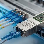
Because 400G transceiver naming is sometimes vendor-specific, always verify the exact part number and standards compliance. Examples commonly referenced in optical networking procurement include high-speed SR4 modules in QSFP-DD form factors (for example, FS.com SFP/optics style naming for 400G SR4 variants) and DR4/FR4 modules with LC connectors from major vendors. When evaluating a specific SKU, compare the datasheet’s link loss assumptions and DOM implementation details; many teams only check “reach” and then get surprised by differences in optical budget and supported host platforms.

QSFP-DD vs OSFP in optical networking: compatibility and power tradeoffs
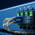
Form factor is often the deciding constraint because hosts are picky about module mechanical fit, lane mapping, and electrical power budgets. QSFP-DD is widely used in switch ports that support 400G Ethernet over 4-lane signaling, while OSFP is common in systems that prioritize higher density and manage thermal design with larger optics. Even if both can support the same “SR4” concept, the host might only support one form factor, or it might have different electrical lane polarity behavior requiring compliant optics.
Compatibility checklist for optical networking hosts
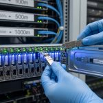
Start with the switch vendor’s optics compatibility list, then confirm that the module type matches the port’s supported standard (for example, 400GBASE-SR4 vs 400GBASE-DR4). Many failures happen when a module “should work” electrically but is blocked by the host’s vendor-specific optics profile or by strict power/EEPROM validation. Also check whether the host expects specific DOM pages and whether your monitoring stack reads standard fields correctly; a misread DOM can cause false alarms even when the link is healthy.
Pro Tip: If you deploy third-party transceivers, test DOM fields in your telemetry pipeline. We have seen teams lose hours because the optics were electrically fine, but the monitoring system flagged the module as “unknown” and triggered automated port flaps.
Real-world deployment scenario: 400G in a leaf-spine optical networking fabric
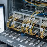
Consider a 3-tier data center leaf-spine topology with 48-port 10G/25G/100G style aggregation and 32 x 400G uplinks on leaf switches. In one rollout, the leaf-to-spine distance averaged 70 m within the row-to-row cabling plant, using OM4/OM5 patch cords with MPO trunks, while spine-to-aggregation used 350 m SMF runs with LC patching. The team selected 400G SR4 for the in-rack and near-row links to avoid expensive SMF optics and to keep operational complexity low. For the longer reach corridors, they switched to 400G DR4 to maintain link margin without requiring FR4-class budget.
Operationally, they validated with optical power readings from DOM (transmit power and receive power thresholds) and confirmed that each corridor met the vendor’s allowable link loss. During acceptance testing, they cleaned MPO/MTP connectors using a verified cleaning workflow and retested with a light meter and/or inspection scope. After go-live, they monitored error counters (for example, FEC/PCS-related counters where available) to ensure the links stayed within normal operating thresholds.

Selection criteria: how engineers choose 400G transceivers for optical networking
Use this decision checklist in order. It is designed to minimize late-stage rework and to align technical optics requirements with procurement and operations.
- Distance and fiber type: Determine whether you need SR4 (MMF) or DR4/FR4 (SMF). Confirm measured end-to-end loss, not just label distances.
- Switch compatibility: Check the host vendor’s supported optics list for the exact port and form factor (QSFP-DD vs OSFP). Validate electrical lane mapping requirements.
- DOM and telemetry requirements: Ensure the transceiver supports the DOM features your monitoring stack expects, including key diagnostics and threshold behavior.
- Operating temperature and airflow: Confirm the module’s temperature range and your rack’s minimum/maximum inlet temps. Thermal margins matter for long-running high-density racks.
- Budget and total installed cost: Include spares strategy, expected failure rates, cleaning supplies, and potential re-cabling. Third-party optics can reduce unit price but may increase validation effort.
- Vendor lock-in risk: Evaluate the risk of optics being “non-interchangeable” across switch generations, especially for monitoring and firmware validation.
- Standards compliance and optics class: Prefer modules aligned with IEEE 802.3 physical layer requirements and stated performance parameters from the datasheet [Source: IEEE 802.3].
Cost and ROI note: what to budget for optical networking transceivers
Pricing varies by vendor, speed, reach, and whether you buy OEM or third-party optics. In many enterprise and data center purchases, 400G SR4 modules tend to be cheaper than long-reach SMF options, but the total cost depends on your fiber plant. If your MMF corridors are short and well maintained, SR4 can reduce both optics cost and operational complexity; if your fiber is aging or connector loss is high, the extra cost of cleaning, testing, and potential re-termination can erase the savings.
For ROI, consider total cost of ownership (TCO): power consumption (transceiver draw plus host thermal impact), spares inventory, and downtime risk. OEM transceivers often price higher but can reduce compatibility and validation time; third-party optics may cut unit cost, but you should run a structured acceptance test to prevent port flaps and monitoring false positives. In practice, the cheapest module is the one that stays up with predictable diagnostics in your environment.
Common mistakes and troubleshooting tips in optical networking
Below are frequent failure modes teams hit during 400G optical networking bring-up. Each item includes a likely root cause and a practical fix.
Link comes up but performance counters show errors
Root cause: Marginal optical budget caused by connector insertion loss, contaminated MPO/MTP endfaces, or patch panel damage. At 100G-per-lane, small losses can push the receiver near sensitivity limits.
Solution: Inspect and clean connectors with a validated workflow, then measure receive power via DOM. If you see large lane-to-lane variation, re-seat fiber, replace suspect jumpers, and re-check polarity/mapping (especially on MPO harnesses).
Module is rejected by the switch or stays in “not supported” state
Root cause: Form factor mismatch (QSFP-DD vs OSFP), unsupported optics standard on that port, or strict EEPROM/DOM profile validation.
Solution: Confirm the port supports the exact standard (SR4 vs DR4 vs FR4) and form factor. Use the vendor’s compatibility list and, if using third-party optics, test a single module first and verify DOM reporting fields before scaling.
Intermittent flaps under thermal load
Root cause: Insufficient airflow or rack inlet temperatures exceeding module thermal design points. Some modules show higher error rates when transceiver temperature rises, even if the link “mostly works.”
Solution: Validate airflow direction, baffle installation, and fan speed setpoints. Track module temperature via DOM and compare against the datasheet’s operating range. Improve cabling airflow clearance and ensure no obstructed vents near the port bank.
“Works on day one” then degrades after patch changes
Root cause: Polarity changes or MPO harness misalignment during re-cabling. In ribbon/MPO systems, a single incorrect polarity mapping can reduce signal quality or break the link.
Solution: Use consistent MPO polarity labeling (and document it). After any patch change, run a link test and verify DOM receive power per lane rather than relying only on “link up” status.
Decision matrix: which transceiver option fits your optical networking goal
Use this matrix to compare SR4 vs DR4 vs FR4 in a typical selection process. Scores are practical heuristics, not a substitute for the exact vendor datasheet and your measured link loss.
| Criteria | SR4 (MMF) | DR4 (SMF) | FR4 (SMF) |
|---|---|---|---|
| Best for distance | Short (tens to ~100 m) | Mid (hundreds of meters) | Long (kilometers) |
| Fiber plant cost | Lower if MMF already exists | Moderate if SMF available | Higher if SMF build is required |
| Operational sensitivity to connectors | High (MPO cleanliness is critical) | Medium (LC is easier to handle) | Medium to high (budget margins can be tighter) |
| Switch compatibility risk | Medium (form factor still matters) | Medium | Lower to medium if host supports long-reach profiles |
| Typical power/thermal impact | Often lower than long-reach | Moderate | Moderate to higher depending on vendor |
| Monitoring/DOM maturity | Usually mature across vendors | Usually mature | Usually mature |
Which Option Should You Choose?
If you have a predominantly in-rack or near-row topology with good MMF and verified MPO hygiene, choose 400G SR4 to minimize cost and deployment complexity. If you need to cross longer corridors on existing SMF with manageable patching, choose 400G DR4 as the most common “works in real life” middle ground. Choose 400G FR4 when you truly need multi-kilometer reach and your link budget is validated; otherwise, FR4 can add cost and reduce margin headroom for connector and aging effects.
Next step: pull your switch optics compatibility list, then map each physical corridor to SR4/DR4/FR4 based on measured loss, and finally run a small pilot with DOM-based validation. For additional background on optics behavior and diagnostics, see optical networking monitoring and DOM.
FAQ
What is the main difference between SR4, DR4, and FR4 in optical networking?
The difference is primarily fiber type and reach targets: SR4 is short-reach over MMF (often ~850 nm class), while DR4 and FR4 are direct-detect SMF options around ~1310 nm with longer reach. Your choice should be driven by measured link loss and connector quality, not just advertised distance [Source: IEEE 802.3].
Do I need DOM for 400G optical networking deployment?
DOM is strongly recommended because it enables transmit/receive diagnostics and temperature/power telemetry. Many operators use DOM thresholds to predict degradation before links fail; without it, troubleshooting becomes slower and more reactive.
Can I mix OEM and third-party 400G transceivers in the same switch?
Often you can, but you must validate compatibility on your exact switch model and port profile. The biggest risk is not the optical physics; it is host validation, EEPROM/DOM expectations, and telemetry pipeline interpretation.
Why do 400G links sometimes fail even when “reach” seems sufficient?
Because reach depends on link margin, which includes connector insertion loss, patch panel quality, polarity mapping, and worst-case receiver sensitivity. At 400G, small physical-layer issues can push the system beyond its allowable budget.
What connector types should I expect for 400G SR4 vs DR4/FR4?
SR4 commonly uses MPO/MTP connectors for MMF ribbon harnesses, while DR4 and FR4 commonly use LC duplex connectors for SMF. Handling MPO cleanliness is usually the most common operational pain point.
How do I reduce downtime during a 400G optical networking rollout?
Run a pilot on representative corridors, validate DOM telemetry, and standardize cleaning and polarity labeling processes. Keep a defined spare strategy (including both transceivers and key jumpers) so you can isolate physical-layer issues quickly.
Author bio: I build and validate high-speed optical networking links in production data centers, focusing on fast optics qualification and measurable link-margin outcomes. I help early-stage teams find PMF by running tight pilots that de-risk hardware compatibility and operational monitoring before scaling.