Edge computing deployments fail in predictable ways: mismatched transceiver types, marginal optical power budgets, and overlooked environmental limits in remote enclosures. This guide helps network and field engineers implement optical solutions that meet latency and reliability targets in edge use cases such as industrial gateways, retail micro data centers, and distributed video analytics.
Edge computing constraints that directly change optical solutions
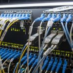
At the edge, you usually trade raw throughput for predictable latency, power efficiency, and serviceability. Your optical link budget is not just a spreadsheet; it is affected by connector cleanliness, patch panel losses, and temperature drift inside the cabinet. In practice, the choice between SR, LR, and ER optics changes fiber type, transceiver thermal behavior, and even how you plan spare parts for field swaps.
Most edge sites also have constrained airflow and higher ambient swings than central offices. That matters for operating temperature ratings and for link margin under worst-case conditions. If you place optics in sealed NEMA or IP-rated enclosures, you should verify vendor thermal guidance and derate expectations during heat soak.
Quick mapping: edge use case to optical profile
- Industrial gateways (10G uplinks over short multimode runs): favor 10GBASE-SR optics on OM3/OM4 with conservative patching.
- Retail edge aggregation across campus fiber: consider 10GBASE-LR or 10GBASE-ER depending on reach and budget.
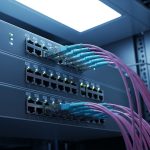
- Video analytics hubs with high fan-in: use 25G/40G/100G optics sized to switch uplink modules and transceiver form factor.
- Rugged outdoor or harsh industrial sites: prioritize temperature-qualified optics and robust connector interfaces.
Pro Tip: Field teams often focus on reach, but the bigger edge risk is link margin variability caused by connector contamination and patch panel aging. Treat every field install as if you will lose 0.5 to 1.5 dB more than the design budget unless you enforce end-face inspection and cleaning.

Transceiver selection: SR vs LR vs ER and form factor reality
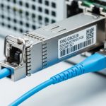
Edge deployments typically start with a known switch platform and its supported transceiver matrix. From there, you choose the optical reach class based on the fiber plant and the expected losses. For Ethernet optics, the line rate and modulation format must match the switch port optics type, while reach class determines wavelength and typical fiber requirements.
For example, 10GBASE-SR uses 850 nm with multimode fiber (OM3/OM4), while 10GBASE-LR uses 1310 nm with single-mode fiber. 25G and 100G families follow similar reach class logic but use different form factors and optics categories (SFP28, QSFP28, CFP2/CFP4 depending on vendor). Always verify the exact transceiver part number support list for your switch model to avoid interoperability surprises.
Spec comparison you can use when planning spares
The table below compares common 10G optical solutions used in edge aggregation. Values vary by vendor and module generation, so treat them as planning baselines and confirm with the vendor datasheet for your exact part.
| Optical solution (example) | Wavelength | Typical reach | Fiber type | Connector | DOM | Operating temp (typ.) | Common use at edge |
|---|---|---|---|---|---|---|---|
| 10GBASE-SR (e.g., Cisco SFP-10G-SR or Finisar FTLX8571D3BCL) | 850 nm | ~300 m (OM3) / ~400 m (OM4) | OM3/OM4 multimode | LC | Often supported | 0 to 70 C (standard) / vendor extended options exist | Short runs inside cabinets and campuses |
| 10GBASE-LR (e.g., FS.com SFP-10G-LR) | 1310 nm | ~10 km | Single-mode (OS2) | LC | Often supported | -5 to 70 C (typ.) | Edge to aggregation across metro fiber |
| 10GBASE-ER (vendor-specific LR/ER variants) | 1550 nm | ~40 km (varies by module) | Single-mode (OS2) | LC | Often supported | -5 to 70 C (typ.) | Long-haul edge backhaul where budget allows |
For Ethernet optics interoperability, the underlying framework aligns with IEEE 802.3 optical interface specifications (e.g., 10GBASE-SR/LR/ER). Confirm your implementation against your switch vendor’s optics compatibility list and the module datasheet. [Source: IEEE 802.3 Ethernet specifications]
DOM and switch behavior at the edge
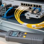
Many modern optical solutions support Digital Optical Monitoring (DOM) over the transceiver interface (commonly via I2C). At the edge, DOM is valuable for early warning: rising receive power, temperature excursions, or aging trends. However, DOM support can vary by switch firmware and how the switch polls the module; validate that the telemetry is actually exposed to your monitoring stack.
If you use third-party optics, confirm whether DOM fields are mapped consistently and whether the switch enforces strict vendor part checks. In some deployments, optics are “compatible” electrically but not “accepted” by the platform due to policy settings or security features.

Deployment checklist: implement optical solutions reliably in the field
When you deploy optical solutions at the edge, your process needs to minimize variability across sites. Start with the switch port capability and planned transceiver part number, then confirm fiber type and measured loss in the actual patching path. Finally, validate optics health using DOM and physical link status after installation.
Step-by-step install workflow
- Confirm switch optics support: verify the exact transceiver SKU is on the vendor compatibility list for your switch model and firmware.
- Validate fiber type: OM3/OM4 for SR, OS2 for LR/ER. Do not rely on “it looks like multimode” assumptions.
- Compute real link budget: include splice loss, connector insertion loss, patch cord losses, and safety margin. Re-check for worst-case temperature and aging assumptions.
- Inspect and clean end faces: use an inspection scope and a validated cleaning method for every LC end before mating.
- Install and verify polarity: confirm transmit/receive mapping for duplex LC runs and label fibers for future service.
- Bring up the link and capture DOM: log Rx power, Tx power, module temperature, and optical alarms right after commissioning.
- Define acceptance thresholds: set alarms for “near low Rx power” and “high module temperature” based on your vendor’s DOM guidance.
Selection criteria decision checklist (engineer-focused)
- Distance and measured attenuation (use OTDR or certified test results).
- Switch compatibility (exact transceiver part numbers and firmware interplay).
- Budget and TCO (OEM vs third-party pricing, expected failure rate, and warranty coverage).
- DOM support and telemetry visibility (monitoring integration, alarm mapping).
- Operating temperature and enclosure conditions (worst-case ambient and heat soak).
- Connector ecosystem (LC vs SC, APC vs UPC, and patch panel availability).
- Vendor lock-in risk (policy enforcement, strict part acceptance, firmware updates).
- Spare strategy (keep matched wavelength/reach class, and plan for field swaps).
Common pitfalls and troubleshooting for edge optical solutions
Edge environments magnify mistakes that central offices can sometimes mask. Below are frequent failure modes seen during deployments, with root cause and concrete fix paths.
Pitfall 1: Link does not come up after install
Root cause: connector polarity/transmit-receive mismatch, wrong duplex mapping, or a cleaning failure that leaves contamination on one end face. In some cases, the transceiver can be electrically detected but optical power never crosses the budget.
Solution: verify fiber polarity end-to-end, then re-clean and re-seat connectors. Use an inspection scope on both ends and confirm the correct Tx to Rx pairing. If available, swap the transceiver with a known-good module to isolate whether the issue is optical or fiber-side.
Pitfall 2: Flapping link under high temperature
Root cause: optics exceeding thermal limits or poor airflow in the edge enclosure. Some modules show high temperature and reduced optical output before the link drops.
Solution: check DOM temperature and optical alarms during the hottest period, not just at commissioning. Improve airflow or add thermal management, and confirm the module’s operating temperature matches your enclosure profile.
Pitfall 3: “Works in lab, fails in production” due to budget mismatch
Root cause: link budget calculations used optimistic connector/splice numbers, or the installed path includes extra patch cords, splitters, or aged connectors. Edge sites also get re-patched during maintenance, silently changing loss.
Solution: re-run budget using actual measured loss from the deployed path. Standardize patch cord lengths and enforce connector inspection. Add margin for real-world variability and document the final “as-built” fiber loss.
Pitfall 4: Third-party optics accepted but monitoring is broken
Root cause: DOM support discrepancies where telemetry fields are not mapped or alarms are not exposed to the switch management plane. Operators then miss early degradation signals.
Solution: verify telemetry ingestion in your monitoring system immediately after commissioning. If DOM data is missing, validate whether the switch firmware supports the module’s DOM implementation and consider an optics vendor that aligns with your monitoring requirements.
Cost and ROI: what to budget for optical solutions at the edge
In most edge rollouts, transceiver unit cost is only part of TCO. You also pay for truck rolls, downtime risk, and the operational overhead of managing spares across many sites. OEM optics often cost more upfront but can reduce compatibility issues and RMA churn.
Typical market pricing varies by speed and reach, but as a practical range: 10G SR modules are commonly in the tens of dollars to low hundreds depending on brand and temperature grade; 10G LR/ER modules can be higher due to single-mode optics complexity. For a multi-site deployment with dozens of transceivers per cluster, the ROI comes from reducing failed installs and minimizing time-to-repair using DOM-driven maintenance.
Also include power and thermal implications. Higher-speed optics and higher optical output can increase switch port power and generate more heat, which can raise cooling costs or push you toward larger enclosures.
For compatibility and operational guidance, consult your switch vendor’s transceiver documentation and the module manufacturer datasheet. [Source: Cisco transceiver documentation] [Source: Finisar and vendor SFP/QSFP datasheets]
FAQ
Q: Which optical solutions are best for edge short runs inside a rack?
For short in-rack or nearby cabinet runs, 10GBASE-SR on OM3/OM4 multimode fiber is often the simplest. It reduces transceiver cost and avoids single-mode cabling complexity, but you must enforce connector cleanliness and validate patch panel losses.
Q: How do I confirm a transceiver will work with my specific switch?
Use the switch vendor’s optics compatibility list for your exact switch model and firmware version. Then confirm the transceiver datasheet matches the required form factor and interface (SFP28 vs SFP+ vs QSFP28, etc.). If you use third-party optics, verify DOM behavior in your monitoring stack.
Q: What DOM metrics should I monitor at edge sites?
Monitor Rx optical power, Tx optical power (if available), module temperature, and any vendor-defined optical alarm thresholds. Capture baseline values right after commissioning so you can detect drift and schedule maintenance before link instability occurs.
Q: Can I mix optical solutions of different vendors in the same edge deployment?
Yes, electrically, but operationally it can be risky if switch acceptance policies differ or if DOM telemetry behaves differently. Standardize part numbers per link type and keep spares consistent so troubleshooting remains fast and predictable.
Q: What is the most common cause of intermittent link drops at the edge?
Thermal stress combined with marginal optical cleaning is a frequent driver. Another common cause is budget drift from re-patching, which changes connector counts and insertion loss without updating documentation.
Q: Are there standards I should reference when planning optical solutions?
For Ethernet optical PHY behavior, IEEE 802.3 provides the baseline for SR/LR/ER families and link characteristics. For deployment practice, rely on vendor datasheets for power class, DOM support, and temperature ratings, plus ANSI/TIA cabling guidance for fiber handling and testing.
Optical solutions for edge computing succeed when you treat transceivers, fiber loss, and thermal constraints as one system, not separate checkboxes. Next, align your cabling and testing workflow with fiber testing and link budget best practices so your acceptance criteria match the as-built reality.
Author bio: I have 10+ years deploying Ethernet