In long or high-capacity fiber runs, pushing transmit power can invite a quieter enemy: Stimulated Brillouin Scattering (SBS). This article helps network engineers and field technicians choose a high power SFP module that meets throughput targets without crossing SBS thresholds that can collapse signal quality. You will get practical selection criteria, a deployment scenario with real link numbers, and troubleshooting steps grounded in telecom standards and vendor guidance.
Why SBS shows up when you raise transmit power
SBS is a nonlinear interaction between light and acoustic phonons in optical fiber. As launched power increases, a backward-propagating Stokes wave can grow, stealing energy from the forward signal. The result is often a combination of elevated error rates, receiver power fluctuations, and in severe cases, a sudden “cliff” in performance.
From an engineering standpoint, SBS risk rises with effective interaction length, narrow linewidth, high launched power, and fiber type (core composition and acoustic properties). The fiber’s SBS threshold is not a single constant; it depends on modulation format, spectral width, temperature, and the precise launch conditions. For reference, SBS behavior and modeling are discussed across telecom literature and are reflected in how vendors specify “maximum launch power” and recommended operating envelopes in datasheets.
Operationally, SBS is most often encountered in systems that combine high power optics with either long spans or tight spectral linewidth. While many 10G and 25G transceivers are designed to operate safely within their specified power budgets, “high power” variants can reduce margin if you also use long patching, passive splitters, or unexpected fiber routing.
High power SFP specs that matter for SBS headroom
When selecting a high power SFP, engineers should treat SBS headroom like a safety margin on a bridge: you need the load rating, the environmental conditions, and the failure mode. Start with the module’s optical parameters and compare them to what your switch and link budget require. Then verify connector cleanliness, fiber attenuation, and any additional losses that might cause you to overcompensate with higher transmit power.
| Spec category | What to check | Why it affects SBS risk | Typical values (examples) |
|---|---|---|---|
| Data rate / interface | 10GBASE-SR / 10GBASE-LR / 25G variants (if applicable) | Different modulation formats and receiver sensitivity change the power you need | 10.3125 Gb/s (10GBASE-R), 25 Gb/s for newer families |
| Wavelength | 1310 nm vs 1550 nm | SBS is more prominent in certain bands and system designs; 1550 nm links often face tighter SBS constraints | 1310 nm or 1550 nm class optics |
| Reach / span length | Max link distance and any patch cord overhead | Longer effective lengths increase SBS interaction | 10 km to 80 km depending on module class |
| Transmit power (Tx) | Launch power into fiber (not just “rated” power) | Higher Tx increases likelihood of SBS growth | Often specified as a min/max; “high power” may sit near the upper end |
| Receiver sensitivity | Required Rx power at the switch input | If sensitivity is weaker, you may over-launch to compensate | Class-dependent; verify datasheet for BER targets |
| Optical power budget | Include connectors, splices, splitters | Unexpected losses tempt higher launch; SBS margin shrinks | Use vendor budget and your loss inventory |
| Operating temperature | Module case temperature range | Temperature affects laser characteristics and spectral behavior | Common ranges include industrial and extended commercial |
| DOM / diagnostics | Digital Optical Monitoring support | Enables detection of drift before SBS becomes catastrophic | DOM typically reports Tx power, Rx power, bias, temperature |
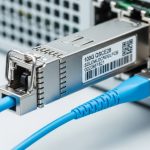
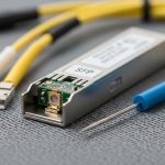
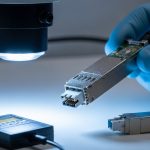
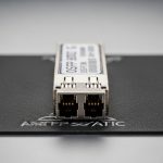
To anchor this in real hardware, many enterprise and carrier networks use SFP/SFP+ optics such as Cisco part numbers (e.g., Cisco SFP-10G-SR) and third-party compatible models from vendors like Finisar or FS. As examples of how you might see “high power” behavior in practice, optics families from Finisar and FS.com often specify strict launch power ranges and recommended fiber types in their datasheets. Always treat those ranges as binding constraints, not suggestions, especially for high power SFP configurations.

Deployment scenario: where SBS shows its teeth
Consider a 3-tier data center leaf-spine topology extended to a regional recovery site. In a typical setup, leaf switches aggregate to spine switches, and a pair of 10G links carry replication traffic over fiber routed through a long campus. Suppose you run two 10 km spans of singlemode fiber with 0.35 dB/km attenuation, plus 1.5 dB connector/splice losses per direction, and you add 2 dB for patching and slack loops. Your switch requires an Rx power no worse than -14 dBm for the specified BER.
Now imagine an engineer chooses a high power SFP variant to maximize margin for future moves. The module’s upper launch spec is used, and the team also cleans fibers late in the lifecycle. If the deployed effective length increases (for example, rerouted patch panels add additional span), SBS headroom can shrink. During a maintenance window, you might observe a pattern: Tx power is stable per DOM, but Rx power shows sudden degradation correlated with certain traffic patterns—especially when the system loads a narrow spectral component.
This is why SBS mitigation is not purely “lower power.” The safest approach is to keep within the vendor-recommended launch range, validate your link loss inventory, and monitor error counters and DOM trends continuously. IEEE 802.3 defines optical link behaviors at the Ethernet layer, but SBS is a physical-layer nonlinear effect, so your best defense is operational discipline plus optical diagnostics.
Selection checklist for high power SFP in SBS-sensitive links
Use this ordered decision list as a field-ready checklist. It is designed to prevent the common failure mode: buying a module that “should work” in a bench test, then losing margin in the real plant.
- Distance and effective length: Confirm actual fiber route length, not just the nominal “reach.” Include patch cords, splices, and any splitters.
- Fiber type and band: Identify core type and whether you are in a band where SBS constraints are tighter (commonly relevant for long-reach designs).
- Launch power discipline: Compare module max Tx to your required power budget. If your budget allows margin, do not automatically pick the highest-power option.
- Switch compatibility: Validate the transceiver family with the switch vendor’s compatibility list where available, and test with your exact optics profile.
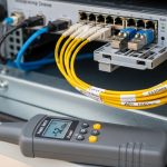
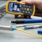
- DOM and alarms: Prefer modules with DOM so you can trend Tx bias, Tx power, Rx power, and temperature; configure thresholds.
- Operating temperature range: Ensure the module is rated for rack and airflow conditions. Temperature drift can change laser output behavior.
- Vendor lock-in risk: If you buy from a single ecosystem, plan spares and RMA handling. Third-party optics can be fine, but confirm compliance with your BER and optical budget requirements.
- Connector and cleaning protocol: If you must push power, you must also protect the link with strict cleaning and inspection practices.
Pro Tip: In the field, SBS-related degradation often correlates with how much “extra margin” you assumed. Teams discover that a link can pass steady-state tests yet fail under certain traffic loads because the effective spectrum driving nonlinear effects is not the same as the lab’s static optical stimulus. Use DOM trends plus interface error counters to catch this early, and avoid launching at the module’s maximum unless the link budget forces it.

Common mistakes and troubleshooting when high power SFP triggers SBS-like behavior
Even when you choose a high power SFP that looks compliant, real networks fail in predictable ways. Below are concrete pitfalls with root causes and fixes.
-
Mistake 1: Over-launching because the datasheet “max” felt safe.
Root cause: Engineers treat maximum Tx as a target rather than a limit, leaving little SBS headroom when effective length grows.
Solution: Recalculate the link loss budget and set the system within the module’s recommended operating envelope; if possible, adjust to a lower launch power profile. -
Mistake 2: Ignoring additional losses from patching and rework.
Root cause: Extra patch cords, dirty connectors, or unrecorded swaps increase attenuation. To restore Rx margin, you might increase Tx power.
Solution: Perform an end-to-end optical loss audit, including connector inspection and cleaning. Confirm Rx power at the switch input after every change. -
Mistake 3: Confusing SBS with simple optical contamination or bad fiber.
Root cause: Dirty connectors can cause intermittent Rx dips, while SBS is a nonlinear power interaction. Both can look like “Rx power instability.”
Solution: Compare behavior across different traffic patterns and power levels. Run a controlled optical test if available, and verify physical cleanliness first (inspection under magnification, correct cleaning method). -
Mistake 4: Missing DOM threshold alerts until the link collapses.
Root cause: DOM is present but thresholds are not configured, so bias and power drift go unnoticed.
Solution: Set conservative alarms for Tx power, Rx power, and temperature; trend them daily. Treat rising bias current or falling Rx power as early warning.
For standards context, Ethernet optical links are defined at the protocol and physical layers by IEEE 802.3. For fiber and cabling practices, ANSI/TIA guidance is often used in plant documentation. SBS itself is a physics phenomenon; the practical mitigation is choosing optics and launch conditions that respect the nonlinear limits described in telecom research and vendor application notes. For deeper background, see [Source: IEEE 802.3] and [Source: ANSI/TIA-568 for cabling practices], plus vendor optics application notes via their datasheet portals.

Cost and ROI: buying high power SFP without buying headaches
Pricing varies widely by wavelength, reach, and whether you need “high power” or extended temperature grades. In many markets, a standard 10G SFP+ transceiver may cost roughly $30 to $120, while higher-spec or long-reach modules can range from $150 to $600+ depending on brand and testing requirements. Third-party compatible optics often reduce purchase cost, but TCO depends on failure rates, lead times, and RMA friction.
ROI comes from fewer outages and faster troubleshooting. DOM-capable modules can reduce mean time to repair because you can pinpoint whether Tx, Rx, or temperature is drifting. If SBS-related incidents cause intermittent packet loss, the hidden cost is not just the transceiver—it is the operational time, escalation, and potential replication lag in storage or backup systems. A cautious approach is to stock a small number of known-good optics and validate against your switch, your fiber inventory, and your power budget before scaling.
FAQ
What makes a SFP “high power” in practice?
A “high power SFP” usually means the module is specified to operate toward the upper end of launch power or offers a higher Tx output within its safety envelope. The critical point is not the label; it is the actual launch power into your fiber after accounting for connectors, splices, and patch cords.
How can I tell if performance loss is SBS rather than contamination?
Contamination typically produces immediate and repeatable degradation tied to cleaning state or connector swaps. SBS often shows a stronger dependence on launched power and can correlate with traffic patterns and spectral behavior. Still, you should always inspect and clean connectors first because it is the fastest and safest remediation.
Should I always choose the highest transmit power available?
No. Higher power reduces margin and can increase nonlinear risks like SBS, especially on longer links. Use the link budget to choose a balanced launch level that satisfies Rx sensitivity without exceeding the module’s recommended operating conditions.
Do DOM diagnostics help with SBS-related issues?
DOM helps because it gives you visibility into Tx power, Rx power, laser bias, and temperature. While DOM cannot directly measure SBS, it can show whether the system is drifting into a nonlinear-risk region or whether the issue is a sudden optical anomaly.
Are high power SFP modules compatible across all switches?
Not always. Some switches enforce vendor-specific transceiver compliance behaviors or have tighter timing and power expectations. Check the switch optics compatibility guidance and test in your environment, especially if you use third-party modules.
Where should I look in standards or guidance?
Start with IEEE 802.3 for Ethernet optical interface expectations and ANSI/TIA for cabling practices that protect link integrity. For SBS specifics, rely on telecom physics references and vendor application notes that translate theory into safe launch limits.
High power SFP modules can be excellent tools when your link budget demands it, but SBS risk turns “more power” into a nonlinear tradeoff. Next, review your actual fiber loss inventory and validate launch power behavior using DOM plus interface error counters—then choose optics that preserve margin rather than consume it fiber link budget basics.
Author bio: I work hands-on with optics deployments in production networks, validating link budgets, DOM alarms, and failure modes under real temperature and cabling conditions. I also review vendor datasheets and standards like IEEE 802.3 to ensure safe, measurable outcomes.
Sources: [Source: IEEE 802.3] [Source: ANSI/TIA-568] [Source: Manufacturer SFP datasheets and application notes, including DOM and maximum launch power guidance]