During DWDM transceiver commissioning, the biggest delays usually come from “it lights up, but it is not behaving” situations: wrong center wavelength, unexpected side modes, or channel drift that only appears under real load. This article helps field engineers and network operations teams use fiber spectrum measurement with an optical spectrum analyzer (OSA) to verify parameters before traffic migration. You will get practical acceptance checks, a spec comparison, and troubleshooting patterns that match what vendors document in troubleshooting sections. The focus is DWDM optics commissioning, not lab-only characterization.
Why spectrum checks matter in DWDM commissioning
In a DWDM system, each transceiver must land on a specific ITUT channel grid (frequency plan), with tight tolerances for center wavelength and acceptable spectral shape. Even when a transceiver reports “link up,” a mis-tuned laser can cause higher bit error rates, inter-channel interference, or failure to meet ROADM mux/demux filtering. With fiber spectrum measurement, you can confirm the spectral footprint of the transmitted signal: center wavelength, linewidth, sideband suppression, and power distribution across the channel. This makes commissioning faster because you catch configuration and optics issues before you involve higher-layer diagnostics.
Most commissioning workflows also need to separate “transceiver problem” from “fiber plant problem.” For example, a connector reflection can distort the observed spectrum or create ghost interference peaks, while a dirty patch panel can reduce received power and mimic a spectral defect. The OSA view gives you an additional axis beyond power alone, especially when channels are packed tightly and filtering is strict. If you follow the IEEE and vendor guidance for optical link budgets and transceiver optics class behavior, spectrum checks become a reliable confirmation step. Reference the IEEE 802.3 family for general optical link principles, and pair it with vendor OSA usage notes in transceiver datasheets.
OSA setup that actually works for transceiver turn-up
The OSA configuration determines whether your measurement is trustworthy. If you use the wrong resolution bandwidth (RBW) or wavelength span, you may smear narrow features or miss side modes that later cause penalties. For DWDM commissioning, you typically want an RBW fine enough to resolve the laser linewidth and a span that covers the expected channel plus margin for adjacent leakage. The goal is repeatability: same instrument settings, same reference points, same calibration routine, and consistent fiber launch conditions.
Instrument settings engineers commonly standardize
- Wavelength range/span: set span to cover the channel center plus at least one adjacent channel width on each side.
- RBW: choose RBW small enough to resolve the expected linewidth; if RBW is too wide, peaks broaden and center wavelength estimates drift.
- Averaging: use moderate trace averaging to reduce noise, but avoid excessive averaging that hides intermittent mode hops.
- Calibration: run the OSA wavelength calibration (internal or external) before a commissioning batch.
- Input path: use a stable tap or splitter with known coupling; document the coupling ratio for power normalization.
Measurement path and coupling choices
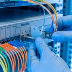
For commissioning, you usually measure from the transmitter side using a fiber tap that feeds the OSA. A common field practice is to use a calibrated splitter and keep it fixed during a deployment window, so coupling changes do not confuse pass/fail decisions. If you must use a patch-based tap, label the fiber and keep connector cleanliness controls strict. The OSA input is often sensitive to reflections and overload; ensure the optical power at the OSA input stays within the instrument’s recommended range in the datasheet.
Pro Tip: If you see “center wavelength looks right” but adjacent channels show unexpected shoulders, check the measurement RBW first. In several real turn-up jobs, engineers used a coarse RBW that smoothed side modes into a false plateau, delaying the root-cause analysis until the RBW was tightened and the side-mode suppression became clearly non-compliant.
Key DWDM transceiver checks you can verify with spectrum data
Not every OSA trace needs to be interpreted the same way. For commissioning acceptance, you typically confirm a small set of parameters that directly map to system performance. These include center wavelength alignment to the DWDM grid, spectral shape (main lobe width and roll-off), and side-mode or out-of-band emissions that can violate mux/demux filtering. Some operators also track drift by comparing traces across time windows after warm-up.
Acceptance targets to document during commissioning
- Center wavelength: verify against the assigned DWDM channel frequency plan, accounting for instrument accuracy and calibration status.
- Optical linewidth: confirm it stays within the expected class range for the transceiver type (narrower is usually safer for dense grids).
- Side-mode suppression: check that adjacent spectral components are below the defined threshold for your system.
- Power and OSNR proxy: while an OSA is not a full OSNR test, you can still spot abnormal spectral power distribution and mode behavior.
- Stability: capture multiple traces over a short interval to detect mode hops or wavelength wander.
Reference examples of transceivers you may encounter
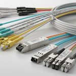
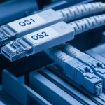
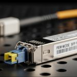
In real deployments, the exact transceiver model varies, but the verification pattern is similar. For example, some coherent DWDM environments use vendor-specific optics with narrow linewidth and tight channel plans, while others rely on tuned lasers with defined grid compliance. If you are commissioning pre-built optics, record model numbers from the module label and align your acceptance criteria with the vendor datasheet. For short examples, you might see common 10G/25G/40G optical module families in coexistence test benches; however, for DWDM channel verification you will usually be dealing with tuned or coherent optics rather than fixed multimode links.

DWDM spectrum measurement spec comparison (what to match before you buy)
Engineers sometimes treat an OSA as interchangeable tooling, but its specs strongly affect commissioning outcomes. Center wavelength accuracy, wavelength calibration method, RBW range, and dynamic range determine whether you can confidently judge channel compliance and side-mode behavior. Before you standardize an instrument, compare its capabilities to your DWDM grid spacing and transceiver spectral requirements. If you are working with 100 GHz spacing, your measurement uncertainty budget must still resolve the channel center well enough to avoid false fails.
| Parameter | Why it matters for DWDM | Typical commissioning requirement | Examples to look for in an OSA / transceiver ecosystem |
|---|---|---|---|
| Wavelength accuracy | Determines whether you can confirm channel center alignment | Sub-channel-grid confidence after calibration | Check OSA datasheet for wavelength accuracy and calibration procedure |
| Resolution bandwidth (RBW) | Resolves linewidth and side modes | Small enough to avoid spectral smearing | Look for RBW settings down to the order of tens of MHz, depending on laser class |
| Wavelength span | Captures adjacent-channel leakage | Channel plus at least one adjacent on each side | Ensure span covers your full DWDM slice during commissioning |
| Input power handling | Prevents OSA overload and trace distortion | Within safe range at the OSA input | Verify tap coupling and OSA maximum input power from datasheets |
| Dynamic range | Detects low-level side emissions | High enough to see suppressed components | Match dynamic range to your side-mode acceptance thresholds |
| Operating temperature | Field stability and drift during long days | Instrument rated for rack-room conditions | Check operating range in the OSA manual |
For authority on optical measurement fundamentals, consult vendor OSA application notes and the relevant ITU channel grid definitions via the ITU recommendations. For general Ethernet optical link behavior, use [Source: IEEE 802.3] as background for link-layer expectations. For instrument-specific guidance, follow [Source: Keysight application notes] or comparable vendor documentation for OSA RBW/span calibration and overload handling. If you are working with coherent systems, also reference coherent vendor measurement guidance.
Selection criteria checklist for field-ready fiber spectrum measurement
When you choose an OSA workflow for DWDM transceiver commissioning, prioritize repeatability and trace interpretability over raw marketing specs. The checklist below reflects how teams reduce commissioning variance across multiple technicians and days.
- Distance and channel plan: identify your DWDM grid spacing (for example 50 GHz vs 100 GHz) and decide the required wavelength resolution to separate adjacent channels.
- Budget vs acceptance certainty: define how tight your pass/fail thresholds are; if thresholds are tight, budget for better wavelength accuracy and dynamic range.
- Switch or mux compatibility: confirm the optical tap method and connector types work with your mux/demux shelves and patch panels.
- Transceiver compatibility: ensure the transceiver type you commission (tuned laser, coherent, etc.) matches what your measurement method can resolve.
- DOM and control-plane alignment: if modules support digital diagnostics (DOM), correlate OSA results with reported laser temperature and bias current to detect mode hopping drivers.
- Operating temperature and drift: confirm the OSA and any adapters/taps remain stable in your field environment.
- Vendor lock-in risk: prefer workflows that do not require proprietary trace formats; document how to export data for your internal acceptance system.

Common mistakes and troubleshooting during commissioning
Even with good instruments, the field introduces variability. The following pitfalls show up repeatedly during DWDM turn-up and are worth baking into your commissioning checklist. Each item includes the likely root cause and a practical fix.
Center wavelength “fails” but the transceiver is fine
Root cause: wavelength calibration drift or incorrect assumption about instrument accuracy after warm-up. Sometimes the OSA was powered on and used immediately without a calibration routine.
Solution: warm up the OSA per the manual, run a wavelength calibration, and re-measure using the same span and RBW. Record the calibration timestamp in your commissioning log so you can reproduce results later.
Side-mode suppression looks worse than expected
Root cause: RBW too wide smears spectral features, and averaging settings can hide narrow components or create artifacts that look like shoulders.
Solution: tighten RBW, reduce span slightly to focus on the channel under test, and capture multiple short traces rather than one long averaged trace. Compare against a known-good reference module or a baseline trace from the same batch.
Unexpected spikes or ghost peaks appear intermittently
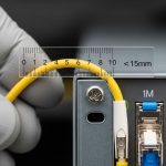
Root cause: connector contamination or micro-bending in the patch path causing reflections and interference ripples. Another frequent cause is a loose adapter that changes coupling each time a technician repositions fibers.
Solution: clean connectors using a controlled process (appropriate inspection, cleaning tools, and end-face handling), then re-seat adapters with consistent torque practices. If you can, keep the fiber path fixed during measurement and avoid moving patch cords after you start the trace capture.
OSA trace is flat or noisy beyond interpretation
Root cause: measurement power outside the OSA input range, either too low (poor SNR) or too high (overload compression). Overload can reduce dynamic range and distort the trace shape.
Solution: verify tap coupling ratio and estimate expected transmitter power at the tap. Adjust coupling (different tap ratio) and confirm OSA input handling limits from the datasheet. Re-check attenuators and any inline patch adapters.
Cost and ROI note: what you should budget for
In many operations teams, the OSA itself is the largest capital expense, but the bigger ROI comes from faster commissioning cycles and fewer truck rolls. For practical budgeting, a field-ready OSA setup can range from low five figures for simpler portable units to high five or six figures for higher-accuracy, high-dynamic-range instruments, depending on RBW capability and calibration features. Third-party transceivers and optics can reduce module cost, but you may incur higher variance in spectral behavior; that can increase retest time and complicate acceptance. TCO should include cleaning consumables, calibrated tap maintenance, connector inspection time, and the operational cost of measurement rework.
From experience, the cheapest path is rarely the best path. If your acceptance thresholds are tight and your DWDM packing is dense, under-spec measurement gear increases false failures and slows deployment. Conversely, if your system uses wider channel spacing and relaxed spectral masks, a lower-cost instrument with adequate RBW and wavelength accuracy can be cost-effective. The key ROI lever is reducing commissioning iteration count by standardizing settings, calibration, and documentation.

FAQ
What wavelength accuracy do I need for fiber spectrum measurement on DWDM channels?
You need enough accuracy to confidently determine channel center within your system’s grid and acceptance tolerance. Start by reading your DWDM frequency plan and the transceiver spectral compliance mask in vendor documentation, then compare that to the OSA’s wavelength accuracy after calibration. If you cannot reconcile the uncertainty budget, you risk false pass/fail decisions.
Should I measure before or after the transceiver is fully installed?
Many teams measure at the rack bench or early in the install to catch defective optics before you commit patching and cabling. However, you still need a post-install measurement to confirm the actual optical path and connector hygiene. A practical approach is “pre-check for gross issues, post-check for final acceptance.”
Can DOM readings replace spectrum checks?
DOM (laser temperature, bias current, and power) helps detect drift mechanisms, but it does not show spectral shape, side modes, or exact center wavelength alignment. Spectrum measurement provides the optical-domain view that directly relates to mux/demux filtering and inter-channel interference. Use DOM as a supporting evidence stream, not a replacement.
Why do I see different traces when I re-patch the same transceiver?
Connector cleanliness, adapter seating, and slight changes in coupling can create reflections that alter the observed spectrum. Even small physical movement can introduce micro-bending or interference artifacts. Fix the measurement path stability first: clean, re-seat consistently, and keep the fiber run fixed during capture.
What is the fastest commissioning workflow that still passes audit requirements?
Standardize OSA settings (RBW, span, averaging), run calibration at the start of each batch, and capture a defined number of traces per transceiver. Export traces and store them with metadata: module model number, channel assignment, OSA settings, calibration timestamp, and tap ratio. This reduces disputes because you can reproduce the measurement conditions during audits.
Where can I find authoritative guidance on OSA measurement practices?
Use OSA vendor application notes for RBW/span selection, overload behavior, and calibration procedures, and use ITU recommendations for DWDM channel grid definitions. For general optical Ethernet link behavior and expectations around optical power and performance, consult IEEE 802.3 references. In practice, combining vendor OSA notes with your transceiver datasheet acceptance criteria gives the most reliable commissioning guidance.
If you standardize your measurement path, lock your OSA settings, and document acceptance criteria tied to the DWDM grid, fiber spectrum measurement becomes a fast, defensible commissioning gate rather than a troubleshooting gamble. Next, review your module and fiber hygiene procedures with connector cleaning and inspection for optical links to reduce reflection-driven artifacts during turn-up.
Author bio: I am a field-focused optical engineer who logs commissioning notes from live DWDM turn-ups, including instrument settings, trace interpretation, and failure mode patterns. I write from on-site experience, translating vendor guidance into repeatable checklists for operations teams.