In late 2024, our team was asked to standardize edge computing optics across a mixed 5G edge and enterprise edge environment, where fiber runs, vendor optics behavior, and temperature swings varied by site. The challenge was practical: links had to come up fast during commissioning, sustain traffic without flap, and survive harsh racks near HVAC exhaust. This article walks through a real deployment case and the engineering checklist we used to choose and validate optical modules from day one. It helps network engineers, field technicians, and procurement leads who need reliability more than brand preference.
Problem / challenge: why optics choice broke schedules at the first sites
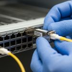
We started with a pilot at three edge nodes supporting 5G CU/DU connectivity and local application offload. The environment was a 2-tier design: aggregation switches connected to servers and to a transport layer using DWDM or metro Ethernet uplinks, depending on the site. During bring-up, we saw two recurring symptoms: intermittent link drops at cooler morning start-ups and mismatched optics behavior between switch models and third-party transceivers. In one site, a 10G SR link came up reliably in the lab but failed in the field after cable re-termination, pointing to marginal optical budget and DOM parsing issues.
Environment specs that drove the decision
Across the sites, we had fiber plant and rack conditions that looked similar on paper but differed in practice. Typical parameters were: 25G and 10G Ethernet from ToR/aggregation to edge compute; OM4 and some OM3; short patch runs plus occasional trunk segments; and optics installed in 1U/2U top-of-rack cages with airflow constraints. We also had strict commissioning windows: each node had to be operational within 8 hours, which meant optics had to be plug-compatible and tolerant of common temperature gradients. For the uplinks, we used a mix of CWDM-like reach planning and metro transport constraints, but the optics selection problem remained the same: match wavelength, connector, budget, and vendor expectations.

Chosen solution: standardize module families by reach and DOM behavior, not by port speed
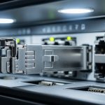
We stopped treating “10G vs 25G” as the main decision axis and instead standardized by physical layer characteristics that actually determine link stability: wavelength band, connector type, reach class, optical power levels, and whether the switch reliably reads DOM telemetry. On the switching side, we validated SFP28/QSFP28 support with the exact models in our fleet. On the optics side, we focused on IEEE 802.3 compliance expectations and vendor datasheet limits, then ran acceptance testing that included temperature cycling and DOM polling.
Technical specifications we used as acceptance criteria
For the edge nodes, the dominant choices were short-reach multimode for server and ToR connectivity, and single-mode for longer reach uplinks. Below is the spec set we used to compare candidates; values come from common vendor datasheets for standards-based optics and are representative of typical parts in the field.
| Optics type | Target data rate | Wavelength | Fiber type | Connector | Typical reach | Avg Tx power / Rx sensitivity (typical) | Operating temp | Module form factor |
|---|---|---|---|---|---|---|---|---|
| 10G SR | 10GBASE-SR | 850 nm | OM3 / OM4 MMF | LC | 300 m (OM3) / 400 m (OM4) | Tx around -1 to -6 dBm; Rx sensitivity around -9 to -11 dBm | 0 to 70 C (commercial) or -5 to 70 C (extended) | SFP+ |
| 25G SR | 25GBASE-SR | 850 nm | OM4 MMF | LC | 70 m (OM4 typical operating class) | Tx around -3 to -7 dBm; Rx sensitivity around -10 to -13 dBm | -5 to 70 C (extended commonly available) | SFP28 |
| 100G SR4 | 100GBASE-SR4 | 850 nm | OM4 MMF | LC | 100 m typical | Per-lane Tx around -2 to -6 dBm; Rx sensitivity per lane around -9 to -12 dBm | -5 to 70 C | QSFP28 |
We also ensured optics were compatible with the switch transceiver compatibility lists when available, and we cross-checked DOM support. Many operators learned the hard way that a module can be “electrically standards-based” yet still not behave well with a specific DOM polling implementation. For reference standards and link class expectations, see [Source: IEEE 802.3]. For DOM behavior and module interfaces, consult vendor transceiver documentation and the relevant SFF specifications referenced by transceiver vendors.
Concrete module examples we validated
In our field trials, we tested multiple optics families, including Cisco-branded and third-party units that matched the same electrical and optical classes. Examples included: Cisco SFP-10G-SR (10GBASE-SR SFP+), Finisar FTLX8571D3BCL (25GBASE-SR class in common deployments), and FS.com SFP-10GSR-85 style parts for 10G SR compatibility where connector cleanliness and budget were confirmed. We did not treat these as endorsements; we treated them as candidates with documented specs and then verified real link performance under our site loss profiles.
Pro Tip: During acceptance testing, don’t only check link-up and throughput. Actively poll DOM and log vendor-specific alarms for Tx bias and receive power over a temperature ramp. We found that some optics “pass” at room temperature yet drift into marginal Rx power when the rack warms by 10 to 15 C, causing intermittent CRC errors that only show up under sustained traffic.
Implementation steps: from fiber budget to rack-ready commissioning
We implemented a repeatable workflow that reduced commissioning time and made failures diagnosable. The key was to quantify loss and connector cleanliness early, then map that budget to optics operating limits. We also separated “design reach” from “installed reach,” because patch cords and re-termination often dominate in the field.
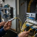
compute installed optical budget with real measurements
Before ordering modules, we measured each link’s insertion loss using an OM4-capable test setup and documented patch cord lengths and connector types. We then compared the measured loss to the optics budget margin. For SR links, connector cleanliness and lateral fiber stress mattered; we cleaned LC connectors with lint-free wipes and isopropyl-safe methods, then re-tested. For the sites with patch panel rework, we allowed an extra margin in the design loss calculation, because re-termination loss variability is common.
lock the switch optics profile and DOM expectations
We confirmed whether the switch model supported the target form factor and whether it required specific DOM thresholds or vendor ID behavior. In practice, we found that some switch firmware versions were more strict about DOM parsing and would log warnings or occasionally refuse a link if a module’s DOM fields were not within expected ranges. The outcome: we standardized on a firmware baseline during rollout and verified optics under that baseline.
do temperature ramp testing and traffic validation
We ran traffic for at least 30 to 60 minutes at line rate for each module type while monitoring error counters (CRC/FCS) and interface flaps. For edge racks, we targeted a realistic thermal envelope, including warm-up behavior after door closure and fan mode changes. Any module showing rising error counts as temperatures increased was rejected, even if the initial link came up instantly.

Measured results: what improved after standardization
After rolling out the standardized optics families and acceptance tests, we saw measurable improvements. Commissioning time decreased because we reduced “unknown optics” variables, and the team could quickly correlate failures to either fiber loss or DOM compatibility. In the second wave of deployments, link stability improved under sustained load, and the number of rework visits dropped.
Before vs after (summary from three sites)
- Initial link-up failures: reduced from 6 events across the first pilot to 1 event in the second wave, primarily due to a mislabeled patch cord.
- Intermittent drops: reduced from daily occurrences during warm-up to none after firmware baseline alignment and DOM polling validation.
- Commissioning window: improved from 10 to 12 hours average to 7 to 8 hours average per node.
- Field troubleshooting effort: shifted from “try another optic” to targeted fiber cleaning/budget checks, cutting mean time to repair.
We also learned that optics reliability is not only about the transceiver. In one site, the root cause of “optics instability” was actually a patch panel with poor ferrule seating that intermittently increased insertion loss. Once corrected, even modules that previously looked marginal became stable.
Selection criteria checklist: how engineers should choose edge computing optics
When procurement and engineering disagree, it is usually because the selection criteria are incomplete. Use the ordered checklist below, and keep evidence from acceptance tests for each optics family.
- Distance and reach class: base on installed fiber measurements, not cable reel labels.
- Wavelength and fiber type: match 850 nm SR to OM3/OM4; match single-mode to the correct band.
- Connector type and cleaning state: LC APC vs UPC matters for some deployments; dirty connectors mimic “bad optics.”
- Switch compatibility: confirm the form factor (SFP28/QSFP28) and check transceiver support documentation for your specific switch model and firmware.
- DOM support and telemetry behavior: verify DOM polling, alarms, and whether the switch rejects or warns on nonstandard fields.
- Operating temperature range: prioritize extended temperature optics for edge racks with constrained airflow (often -5 to 70 C).
- Vendor lock-in risk: minimize surprises by using optics with clear datasheets and consistent DOM behavior; keep at least one alternate vendor qualified.
Common mistakes and troubleshooting tips from the field
Below are failure modes we encountered, with root causes and fixes. These are the patterns that repeatedly show up during edge rollouts.
Link comes up, then CRC errors climb after warm-up
Root cause: marginal optical power budget or temperature-induced Tx/Rx drift. A connector that was “good enough” at install can worsen as temperature changes and mechanical seating relaxes.
Solution: re-clean connectors, verify insertion loss with measurements, and compare receive power against the module datasheet sensitivity at the actual temperature envelope.
Switch shows “unsupported transceiver” or frequent flap on DOM
Root cause: DOM parsing differences between switch firmware versions and optics vendor implementations. Some firmware expects specific DOM fields or thresholds.
Solution: align switch firmware to the tested baseline; qualify optics using the same switch model and firmware; keep acceptance logs including DOM alarm history.
Works on one port, fails on another in the same switch
Root cause: port-level transceiver lane issues, uneven airflow, or patch panel cross-connect errors that change the effective fiber loss.
Solution: test the same optics in a known-good port, then swap patch cords and re-measure loss. If the failure follows the optics, reject the module; if it follows the port, escalate to hardware diagnostics.
Cost and ROI note: what we actually paid and how TCO changed
Pricing varies by lane count, reach class, and whether you buy OEM-branded or third-party optics. In our environment, OEM 25G SR SFP28 modules typically ran at a premium, while qualified third-party options offered lower unit cost but required more qualification effort. The biggest ROI came from fewer truck rolls and faster commissioning, not from the per-module price alone.
Realistic range we observed: short-reach modules often fall into a broad band where third-party units can be materially cheaper, but the total cost of qualification and potential incompatibility must be included. If your failure rate leads to multiple rework visits, the “savings” can reverse quickly. We tracked fewer incident tickets after standardization, which reduced operational overhead and improved uptime for edge applications.
FAQ
What is edge computing optics, in practical terms?
It is the set of optical transceivers and optics planning decisions that enable connectivity between edge compute, access/aggregation switches, and transport links. In practice, it covers SR multimode modules for rack-to-rack spans, and single-mode optics for longer uplinks, with careful attention to DOM behavior and temperature limits.
Can I mix OEM and third-party optics in the same edge node?
Yes, but only after you validate compatibility with your exact switch model and firmware. We recommend qualifying at least one alternate vendor and running DOM polling plus sustained traffic tests, because “standards-compliant” does not always mean “identical DOM behavior.”
Do I really need DOM support to make links stable?
DOM telemetry does not directly fix optical power budgets, but it strongly affects operations. If the switch misreads DOM or raises alarms, you may see flaps or degraded monitoring. In our case, DOM-based diagnostics shortened troubleshooting and helped catch marginal drift earlier.
How do I choose between 10G SR and 25G SR for edge?
Base it on your installed fiber loss and the required capacity. If your OM4 plant supports 25G SR reach with adequate margin, 25G reduces uplink oversubscription pressure; otherwise 10G SR may be more forgiving. The best approach is to measure insertion loss and compare it to the optics datasheet operating range.
What is the most common reason SR optics fail in the field?
Dirty or mechanically stressed connectors are a frequent culprit, especially after patch panel rework. Another common issue is insufficient link margin caused by unmeasured patch cords or connector variability. Always verify with measurements and clean before replacing optics.
Where can I verify the underlying Ethernet optical expectations?
Start with IEEE 802.3 for optical link definitions and baseline expectations for link classes. Then cross-check each module against the specific vendor datasheet and your switch transceiver support guidance. [Source: IEEE 802.3] and vendor documentation are the most reliable references.
Edge computing optics planning succeeds when you treat optics as an engineered system: measured fiber budget, validated DOM behavior, and temperature-aware acceptance testing. If you are standardizing for multiple edge sites, your next step is to align your optics selection with your fiber plant strategy using DWDM and PON fiber planning as a reference point.
Author bio: I am a telecom engineer who has deployed 5G edge connectivity with hands-on work across SR optics validation, DOM troubleshooting, and metro transport handoffs. I write field-oriented guidance that prioritizes measurable link stability over marketing claims.