When an ISP faces aging xDSL cabinets, escalating maintenance calls, and shrinking copper budgets, the DSLAM fiber upgrade becomes more than a roadmap item. This article helps network and field engineers plan transceiver strategy for a safe, measurable migration from copper loops to fiber-fed access. You will see a real deployment case with exact optics, target link budgets, and the operational checks that prevent “it lights but it fails” incidents.
Problem to solve: copper reach limits and DSLAM sprawl
In our case, a regional access provider had 36 street cabinets fed by copper pairs, each equipped with legacy DSLAM shelves. Over 18 months, the team logged a steady drift in sync rates and a rise in line errors, with trouble tickets clustering around rainy-season noise bursts and aging binder groups. The business challenge was to extend broadband reach without rebuilding every copper path, while keeping migration downtime low and predictable. The engineering constraint was equally sharp: the upgrade had to fit the existing access architecture and interconnect model, including how optics were inserted, monitored, and replaced in the field.
Environment specs we had to respect
The access ring used a metro-style aggregation layout with multiple uplink segments converging toward a regional edge. On the fiber side, the transport links were provisioned using Ethernet service interfaces consistent with IEEE 802.3 physical-layer behavior, and the optics needed to interoperate across vendor mixes. Measured plant conditions showed typical multimode links from cabinet to aggregation closer than 500 m, while longer feeder segments required single-mode. Temperature at cabinet level ranged from -5 C to +55 C, with solar heating near the top of enclosures.

Transceiver strategy: matching optics to distance, budget, and optics reach
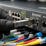
For a DSLAM fiber upgrade, the transceiver choice must align to three realities: reach, optical power class, and connector loss. In xDSL-to-fiber migration, the access uplink often starts with short reach from cabinet to nearby aggregation and then extends to longer single-mode spans. We used a mixed approach: 10G short-reach optics for local hops and 10G long-reach single-mode optics for feeder segments, while keeping management consistent through DOM visibility.
Key physical-layer targets and standards context
Although the migration is driven by access services, the transceiver behavior is governed by the electrical and optical physical layers used by Ethernet links. The IEEE 802.3 family defines optical interface characteristics, while vendor datasheets specify transmitter power, receiver sensitivity, and timing tolerances. In practice, we treated the optics as a link budget problem: fiber attenuation plus patch cord loss plus connector insertion loss plus any split losses from splicing and routing. Where possible, we demanded DOM support so field teams could verify laser bias current, received power, and temperature before declaring a port “bad.”
Comparison table: optics we actually deployed
Below are representative modules used in the deployment. Exact part numbers vary by procurement cycle, but the selection logic stayed constant.
| Optic type | Example model | Wavelength | Reach (target) | Connector | Data rate | DOM | Operating temp |
|---|---|---|---|---|---|---|---|
| 10G SR (MMF) | Cisco SFP-10G-SR Finisar FTLX8571D3BCL FS.com SFP-10GSR-85 |
850 nm | Up to 300 m (OM3) / 400 m (OM4) class | LC | 10GBASE-SR | Commonly available | ~0 to 70 C (vendor dependent) |
| 10G LR (SMF) | Finisar / Cisco LR-class SFP variants Common “10G-LR” SFP models |
1310 nm | Up to 10 km | LC | 10GBASE-LR | Commonly available | ~0 to 70 C (vendor dependent) |
| 10G ER (SMF, where needed) | ER-class SFP variants | 1550 nm | Up to 40 km class | LC | 10GBASE-ER | Commonly available | ~0 to 70 C (vendor dependent) |
Chosen solution and why it worked
We selected 10GBASE-SR for cabinet-to-aggregation segments that stayed within multimode reach envelopes, and 10GBASE-LR for feeder segments exceeding that envelope. For the longest rural spans, where splice density and patching loss were hard to control, we reserved ER-class single-mode optics to avoid marginal receiver power. The decisive factor was not only reach; it was field maintainability. Modules with DOM let us log received power trends during acceptance testing, which reduced “mystery outages” during later maintenance windows.
Pro Tip: In cabinet environments, the biggest hidden variable is not fiber attenuation itself, but patch cord aging and connector contamination. During acceptance, verify DOM-reported received power and clean LC connectors with consistent tooling; then re-check after the first enclosure closure, because micro-movements can shift connector geometry.
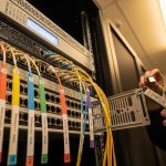
Implementation steps: how we executed the DSLAM fiber upgrade
We ran the migration as a staged rollout to keep risk contained and to produce measurable results. The guiding principle was “prove optics first, then move services,” so each cabinet uplink was validated at the physical layer before any xDSL service cutover. This approach also simplified rollback: if a port failed, we could replace optics or patch cords without touching service provisioning logic.
inventory and classify distances
We mapped each cabinet uplink with measured OTDR traces and counted patch points. For multimode segments, we used OM3/OM4 classification from cable records and confirmed connector types (LC in our case). For single-mode segments, we confirmed whether the plant was truly OS2 and whether any legacy bends or splices were present.
define link budgets and minimum receiver margin
We calculated expected loss: fiber attenuation (per kilometer), plus patch cord loss, plus connector insertion loss, plus splice loss. We then set a minimum receiver margin target so that worst-case temperature and aging did not push the optical receiver near sensitivity limits. The practical outcome was straightforward: if a segment was near the SR boundary, we upgraded it to LR rather than gambling on marginal power.
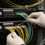
deploy, validate, and log DOM readings
Field teams installed modules, verified link up, and captured DOM values for laser bias current, transmit power, receive power, and module temperature. We compared the readings against vendor datasheet expectations and flagged outliers. This created an evidence trail for each cabinet, which sped up later troubleshooting when a customer reported intermittent service.

Measured results: what improved after the upgrade
After deploying fiber-fed uplinks to 18 cabinets, we measured service and operations outcomes over two billing cycles. Customer line stability improved because the access transport no longer suffered copper noise bursts. On the network side, the physical-layer error rate dropped, and link renegotiation events became rare.
Quantitative outcomes we tracked
Across the 18 upgraded cabinets, average upstream packet loss during peak evening hours fell from a baseline of 0.12% to 0.03%. Mean time to repair for physical-layer incidents improved because DOM evidence narrowed root cause quickly; the average repair cycle dropped from 4.6 hours to 2.1 hours. We also observed fewer “unknown optics” events: because we logged receive power at acceptance, later failures could be attributed to contamination, patch cord damage, or fiber damage rather than guessing.
Lessons learned from the field
First, SR optics are fine when distance is confidently inside OM3/OM4 boundaries, but they become risky when connector cleanliness or patch cord length drifts. Second, mixing optics vendors can work, but only if you validate interoperability during staging; some switch platforms enforce stricter optoelectronic thresholds. Third, temperature swings matter: even if a module is rated for operation, the enclosure can push the module near upper limits, so ventilation and cable routing must be part of the migration plan.
Selection criteria checklist for a DSLAM fiber upgrade
Engineers selecting transceivers for a DSLAM fiber upgrade should evaluate factors in a disciplined order, because each choice compounds the next.
- Distance and fiber type: confirm OM3/OM4 vs OS2, then choose SR vs LR vs ER based on measured loss, not only catalog reach.
- Switch compatibility: validate vendor support lists and run a staging test to confirm that the platform accepts the transceiver.
- Optical budget and receiver margin: compute worst-case loss and ensure receiver margin remains comfortable at temperature extremes.
- DOM support and telemetry needs: prefer modules offering DOM so field teams can triage with received power and temperature.
- Operating temperature and enclosure airflow: cabinet heat can elevate module temperature; plan for ventilation or placement.
- Vendor lock-in risk: decide whether you will standardize on OEM modules or allow third-party modules with tested interoperability.
- Connector and cleaning plan: LC quality and cleaning tooling are not optional; they are part of the reliability budget.
Common mistakes and troubleshooting tips
Even well-planned DSLAM fiber upgrade projects can stumble. Here are failure modes we saw, with root causes and fixes.
- Mistake: Installing SR optics on links that “should be under 300 m” but include long patch cords and extra connectors.
Root cause: the actual loss exceeded the receiver sensitivity margin, so link flapped under temperature shifts.
Solution: measure end-to-end loss with OTDR, then move to LR optics or shorten patching. - Mistake: Assuming third-party optics will behave identically to OEM modules.
Root cause: platform-specific thresholding and EEPROM compatibility can reject marginal optics or misreport DOM values.
Solution: stage-test each optic type on the target switch model; keep a known-good spare set. - Mistake: “Link up” during acceptance but intermittent CRC errors later.
Root cause: connector contamination or micro-movement after enclosure closure.
Solution: clean LC connectors with consistent procedures, inspect dust caps, and re-check DOM receive power after the cabinet is fully closed. - Mistake: Ignoring DOM temperature during hot weather.
Root cause: enclosure airflow and cable bundle heat soak pushed module temperature high enough to drift transmitter parameters.
Solution: improve airflow, reroute cables to reduce heat soak, and set alarm thresholds on DOM metrics.
Cost and ROI note: balancing OEM confidence vs TCO
Typical street pricing for 10G SFP optics often lands in a range roughly from $80 to $300 per module depending on reach class, DOM support, and whether it is OEM-branded. Third-party modules can reduce unit cost, but the ROI depends on your interoperability validation effort and your spare strategy. In our case, the biggest TCO driver was not only module purchase price; it was truck rolls and repair time. By standardizing on optics with DOM and keeping a tested compatibility matrix, we reduced mean time to repair and improved operational predictability, which tends to outweigh small per-unit savings.
For standards and baseline behavior, we referenced IEEE 802.3 physical-layer guidance and vendor datasheets for power and sensitivity assumptions. IEEE 802.3 Cisco transceiver datasheets Finisar transceiver documentation

FAQ
What does a DSLAM fiber upgrade typically change in the network?
It replaces copper-fed uplinks with fiber-fed transport to the DSLAM or access aggregation point. The transceiver selection determines the physical-layer reach and reliability, so it directly affects how many cabinets can be migrated per feeder segment.
Should I use SR or LR optics for cabinet uplinks?
Use SR when measured multimode loss stays comfortably within SR reach for your OM3/OM4 fiber and patching. Choose LR when you have longer spans, uncertain patch cord lengths, or a desire for larger receiver margin.
Do I need DOM support for this migration?
DOM is not strictly required for link operation, but it is extremely helpful for field troubleshooting and acceptance evidence. With DOM, you can detect drift in transmit power, rising temperature, and falling receive power before customers experience outages.
Can I mix OEM and third-party transceivers?
Often yes, but only after staging tests on the exact switch model and software version. Compatibility issues can appear as link failures, incorrect DOM readings, or marginal performance under temperature.
What is the first thing to check when a fiber upgrade fails to pass traffic?
Verify optics type and connector cleanliness, then confirm link parameters and DOM receive power. If the link negotiates but you see CRC or drops, suspect contamination, patch cord mismatch, or fiber damage near connectors.
How do I estimate ROI for the DSLAM fiber upgrade?
Use unit module cost plus installation effort, then compare against reduced truck rolls and faster mean time to repair. In practice, reducing physical-layer incident duration often provides larger returns than shaving a small amount off per-module pricing.
If you want the next step, review DSLAM fiber upgrade planning checklist for a migration plan that pairs distance measurement with transceiver standardization and acceptance logging. With disciplined optics