When an SFP link refuses to come up, the outage feels sudden, yet the cause is often quiet: a marginal optics pair, a dirty connector, or a timing mismatch hidden behind vendor firmware. This article helps network and facilities teams performing data center repair during leaf-spine incidents, maintenance windows, or slow degradations. You will get a practical troubleshooting flow, a spec comparison table, and a decision checklist that aligns with reliability thinking and ISO 9001 evidence habits.
Why SFP link failures look random in real racks
In a typical 3-tier data center, a ToR switch may show Link Down while the far-end remains stable, because physical layer negotiation depends on laser bias, receive sensitivity, and optics cleanliness. IEEE 802.3 defines Ethernet PHY behavior, but the observed symptoms are shaped by optics type (SR vs LR), fiber grade, and connector contamination. During a field response, I have seen “intermittent” links that correlated with a single patch panel bank where cleaning had been skipped for months. The repair mindset should therefore treat optics and cabling as measurable systems, not guesses.
Evidence first: what to capture during triage
Start with timestamps and switch port identifiers, then collect: interface counters, admin state, negotiated speed, and transceiver diagnostics (DOM if available). Record optical receive power (dBm), transmit power (dBm), and temperature from the SFP DOM page, if your platform supports it. For ISO 9001 style traceability, attach a photo of the transceiver label and the fiber connector inspection results. This reduces repeat failures and supports corrective action closure.
Specifications that actually change failure outcomes
SFP link behavior is tightly coupled to wavelength, reach, and optical power budgets. Even when the data rate matches, an optics mismatch can cause marginal receivers to fail under temperature swings, especially in high-density pods with strong airflow gradients. The table below compares common 10G SFP families used for intra-data-center links and highlights the parameters you should verify during data center repair.
| Transceiver model examples | IEEE alignment | Wavelength | Reach (typical) | Connector | DOM/diagnostics | Operating temp | Typical power class |
|---|---|---|---|---|---|---|---|
| Cisco SFP-10G-SR, Finisar FTLX8571D3BCL, FS.com SFP-10GSR-85 | 10GBASE-SR | ~850 nm | ~300 m over OM3 (varies by vendor) | LC duplex | Yes (SFF-8472/DOM) | 0 to 70 C (commercial) or -5 to 85 C (varies) | Low to moderate optical power |
| 10GBASE-LR (vendor equivalents) | 10GBASE-LR | ~1310 nm | ~10 km over single-mode | LC duplex | Yes | Often wider range | Higher budget for long reach |
| Direct attach copper (DAC) SFP+ (if used) | 10GBASE-CR | N/A | ~1 to 7 m (varies) | SFP edge | Varies | 0 to 70 C typical | Electrical link power |
Sources for foundational behavior include IEEE 802.3 for Ethernet PHY requirements and vendor datasheets for DOM and link budget details. For DOM interpretation, follow SFF-8472 guidance as reflected in transceiver vendors’ documentation. Source: IEEE 802.3 Source: SFF and transceiver ecosystem references via SNIA
Pro Tip: If DOM shows receive power is within spec yet the link still flaps, treat it as a physical-layer variability problem: inspect for hairline fiber cracks, check patch panel strain relief, and verify that the LC latch fully seats. Optical power can look “fine” while micro-misalignment triggers intermittent receiver loss.

Field workflow for SFP link failure repair
Use a consistent sequence so each repair is repeatable and auditable. In my experience, the fastest path is to separate “compatibility” from “optics and fiber condition,” then validate using measurable optics readings. The flow below works whether you are swapping a single port or executing a batch replacement during a scheduled window.
Step-by-step triage
- Confirm port configuration: match speed and encoding expectations; verify the switch profile and any optics type settings.
- Validate transceiver identity: read DOM vendor/part info; confirm it is the correct type for the fiber (SR vs LR, MM vs SM).
- Check optical path: measure receive power in dBm; compare against vendor thresholds and link budget assumptions.
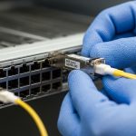
- Inspect and clean: clean the ferrules using lint-free swabs and approved cleaning method; re-seat connectors firmly.
- Swap test: move the SFP to a known-good port and/or swap the far-end optics to localize the fault.
- Examine fiber: inspect end faces with a scope; check for kinks, bends, and patch panel strain.
Decision checklist engineers should follow
- Distance and fiber type: OM3/OM4/OS2 match for SR or LR; verify link length vs vendor reach.
- Budget and receiver margin: ensure receive power stays in the safe operating range across temperature.
- Switch compatibility: confirm the platform supports the transceiver class; watch for vendor lock-in behavior.
- DOM support: prefer transceivers that provide stable, readable diagnostics for faster MTTR.
- Operating temperature: check rack airflow; confirm the optics temperature stays within its rated envelope.
- Vendor lock-in risk: evaluate OEM vs third-party sources with documented compatibility and warranty terms.

Common mistakes and troubleshooting tips that save hours
Even disciplined teams fall into recurring traps. Below are concrete failure modes I have seen during data center repair calls, along with root causes and fixes.
- Mistake: Cleaning only one end. Root cause: contamination often exists on both mating ferrules, especially in high-touch patch panels. Solution: clean both ends, inspect under magnification, and re-seat before retesting.
- Mistake: Replacing optics without checking fiber type. Root cause: an SR transceiver on the wrong fiber grade or a mismatch between MM and SM can yield unstable or dead links. Solution: verify patch labels, trace the fiber jacket, and confirm OM3/OM4/OS2 designation.
- Mistake: Ignoring DOM temperature and power drift. Root cause: optics can be within “nominal” range yet degrade under airflow or thermal cycling, causing flaps. Solution: log DOM over several minutes and correlate with rack inlet temperatures and port flapping timestamps.
- Mistake: Using “compatible” parts with weak documentation. Root cause: third-party optics may report diagnostics differently or hit stricter thresholds on certain switch firmware. Solution: require vendor test evidence, compatibility lists, and warranty terms; keep a controlled lab validation step.
Cost, ROI, and reliability math for repair decisions
In many enterprises, OEM SFPs cost roughly $80 to $200 each for 10G SR-class modules, while reputable third-party options may land around $35 to $110 depending on reach and warranty. The true TCO often includes downtime cost, truck roll time, and the cost of repeated repairs when optics are swapped blindly. MTBF for optics is not always published consistently, but field reliability improves when teams use DOM telemetry, maintain cleaning discipline, and keep spares matched to switch compatibility.

FAQ: SFP link failures during data center repair
Q: What is the fastest way to tell whether the SFP or the fiber is failing?
A: Use a swap test: move the SFP to a known-good port, or swap the far-end optics first. If the fault follows the transceiver, you have a strong candidate for replacement; if it stays with the fiber path, inspect and clean the connectors and measure Rx power.
Q: How do I interpret DOM receive power in dBm?
A: Compare the Rx power reading to the vendor’s recommended operating range and your expected link budget for the configured fiber type. If Rx power is near the threshold, small connector contamination or added loss from patch panels can push the link into failure.
Q: Can I mix different vendor SFPs on the same link?
A: Often yes for standards-based optics, but practice varies by switch firmware and diagnostics thresholds. Validate in a maintenance window, and prefer transceivers with consistent DOM behavior