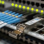
CFP2-DCO module choice for 100G service provider links
In a service provider network, a 100G outage is rarely “just a bad transceiver” — it is usually a mismatch between optical budget, switch optics, and environmental constraints. This case study shows how an engineering team selected a CFP2-DCO module for dense metro links and validated it with measurable BER and power levels. You will get practical selection criteria, implementation steps, and troubleshooting patterns that field teams can reuse.
Problem / challenge: 100G expansion without disrupting live metro traffic
The challenge began during a capacity refresh for a metro aggregation ring. The operator had 16 sites with dual-homed 100G handoff, each site using a mix of vendor optics and patch-panels. Over a 6-week cutover window, they needed to add 32 new 100G circuits while keeping existing traffic stable and meeting strict SLA thresholds. The internal constraint was simple: if a new optic could not be validated quickly, it would miss the deployment window.
Engineering suspected their main failure risks would be optical power margin and thermal behavior, not only wavelength accuracy. Many links were 20 km to 40 km over OM4-to-OS2 transitions and patching that added unpredictable insertion loss. The team also wanted digital optics features to support monitoring and faster troubleshooting during live operations.
Environment specs: what mattered in the lab and in the field
Before selecting hardware, they characterized each link path and the transceiver interface requirements. They collected fiber plant loss with an OTDR trace and end-to-end insertion loss with a light meter, then compared it to the planned optical budget. On the switching side, they confirmed the line card supported CFP2 form factor at 100G with the expected electrical interface and DOM telemetry behavior.
From a standards perspective, they anchored expectations to IEEE Ethernet PHY behavior and vendor implementation notes for 100G optics, and they used vendor datasheets for laser wavelengths, receiver sensitivity, and DOM registers. For optics behavior and interface expectations, they also referenced IEEE 802.3 specifications for 100G physical layer alignment and signal integrity requirements. [Source: IEEE 802.3 standard, 100GBASE specifications]
| Key spec | Typical CFP2-DCO module target | Field relevance in this case |
|---|---|---|
| Form factor | CFP2 | Must fit existing chassis and vendor line cards |
| Data rate | 100G | Direct replacement for 100G circuits |
| Wavelength / grid | DWDM-ready coherent optics (DCO concept) | Needed for consistent alignment across metro spans |
| Reach | Commonly 20 km to 80 km class depending on configuration | Matched the observed 20–40 km span set |
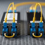
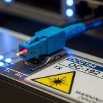
| Connector | LC (typical for pluggable optics) | Compatible with existing patch panels |
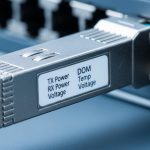
| DOM / telemetry | Temperature, laser bias, received power (vendor-specific registers) | Reduced mean time to repair during cutover |
| Operating temperature | Typically industrial or extended ranges (vendor-defined) | Important for cabinets with poor airflow |
| Power consumption | Vendor-dependent, often a known chassis budget item | Avoided line-card thermal throttling |
In practice, the team treated the “DCO” requirement as a controllability and stability objective: predictable wavelength behavior, robust coherent performance, and reliable DOM reporting so they could automate health checks. The exact optical numbers depend on the specific CFP2-DCO SKU, but the deployment method below remains the same across vendors.

Chosen solution and why: CFP2-DCO module for controlled wavelength and rapid validation
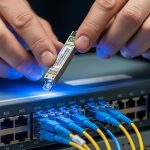
The team selected a CFP2-DCO module SKU that was explicitly supported by their switch vendor compatibility matrix and that provided DOM telemetry for optical health monitoring. They also verified the module’s operating temperature range matched cabinet conditions. To reduce risk, they requested vendor documentation for wavelength accuracy, receiver sensitivity, and recommended optical budget margins.
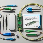
They also compared candidate optics from multiple sources, including OEM-aligned products and third-party options. In similar deployments, engineers often consider models such as Finisar and OEM-equivalent coherent CFP2 offerings (exact DCO part numbers vary by vendor), plus third-party transceivers sold with compatibility guarantees. When evaluating alternatives, they focused on whether the module’s DOM behavior matched the line card expectations and whether the vendor provided BER test data under realistic traffic patterns.
Pro Tip: Do not judge a coherent-capable CFP2-DCO module only by “reach” on the datasheet. In metro plants with patch loss variation, the fastest field wins come from validating receiver optical power thresholds and DOM alarms under worst-case temperature, then scripting those alarms into your NOC runbooks.
Implementation steps: from inventory to measurable results
1) Pre-check compatibility: They confirmed the line card firmware version and transceiver compatibility, then validated that DOM reads succeeded using standard management interfaces. Where the switch allowed it, they enabled transceiver threshold monitoring so that laser bias and receive power alarms were actionable.
2) Build an optical budget: Using OTDR and end-to-end loss measurements, they computed insertion loss including patch panels and splices. They reserved margin for connector aging and cleaning variation, then ensured the planned receive power landed within the module’s recommended operating window.
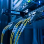
3) Controlled staging: They staged 8 circuits per weekend for early detection of issues. Each circuit used a standardized patching method and verified connector cleanliness. They ran a BER test and monitored error counters for a minimum stabilization period after link bring-up.
4) Cutover and monitoring: During the live cutover, they pinned traffic to expected profiles and compared pre- and post-change link metrics. DOM telemetry was polled at short intervals, and alarm thresholds were tuned to avoid noisy triggers while still catching drift early.

Measured results: what improved after adopting CFP2-DCO
After rollout, the team recorded measurable improvements in both stability and operational visibility. During the first 30 days, all 32 new 100G circuits came up without manual optical rework. They observed that link error counters remained stable within the expected BER test window, and they used DOM trends to confirm that received power stayed inside the planned margin despite minor patch-panel loss variance.
Operationally, the mean time to repair dropped because technicians could pinpoint drift or receive-power alarms rather than guessing. In one incident involving a suspect patch cord, DOM showed a receive-power drop consistent with connector contamination, and the fix completed in under 45 minutes after swapping and cleaning the LC pair.
Cost-wise, they compared OEM-aligned CFP2-DCO modules versus third-party equivalents. OEM modules typically carry higher unit pricing but can reduce compatibility and RMA cycle risk. Third-party modules can lower procurement cost, yet they require stricter validation, especially around DOM alarm mapping and line-card compatibility. Over a year, the team estimated a total cost of ownership advantage only when the validation pipeline prevented “silent incompatibility” and reduced failed deployments.

Common mistakes and troubleshooting tips
1) Assuming datasheet reach equals real reach
Root cause: ignoring patch cord loss, connector reflectance, and splice variability.
Solution: measure end-to-end loss and verify receive power margins against the module’s recommended window; use OTDR to locate high-loss sections.
2) DOM alarms not matching the runbook
Root cause: DOM register mapping differs across vendors, so NOC thresholds may not trigger correctly.
Solution: during acceptance testing, record actual DOM values at idle and under load; update thresholds and alarm interpretation before production cutover.
3) Thermal surprises in cabinets
Root cause: line-card airflow differences and poor ventilation can push transceiver temperature beyond the intended operating range.
Solution: log transceiver temperature and line-card fan behavior during the hottest time window; ensure the cabinet meets vendor airflow guidance and that airflow baffles are installed.
4) Cleaning and connector handling shortcuts
Root cause: LC end-face contamination creates intermittent receive-power drops that look like optical budget issues.
Solution: enforce a cleaning SOP, inspect with a fiber scope, and replace suspect patch cords before concluding the CFP2-DCO module is faulty.
Selection criteria checklist for a CFP2-DCO module
- Distance and optical budget: confirm measured span loss, connector loss, and required receive power margin.
- Switch compatibility: verify CFP2 support on the exact line card model and firmware release.
- DOM support and monitoring: confirm telemetry items you need (temperature, bias, receive power) and how alarms map.
- Operating temperature: match the module’s range to cabinet conditions; plan for worst-case summer operation.
- Vendor lock-in risk: assess whether firmware or alarm mapping forces OEM-only optics in practice.
- Test and acceptance process: require vendor BER data and run a mini-pilot before scaling to dozens of circuits.
FAQ
Q: What exactly is a CFP2-DCO module used for in 100G networks?
A: A CFP2-DCO module is a 100G pluggable optic designed for coherent-capable or DCO-style operation, with DOM telemetry for operational visibility. In practice, it is selected when your plant and switch support coherent/DCO behavior and when you need predictable optical performance and monitoring.
Q: How do I verify compatibility with my switch?
A: Start with the switch vendor compatibility matrix for CFP2 optics and confirm the line card firmware version. Then run an acceptance test that includes DOM readout, link bring-up, and BER or error counter validation under load. [Source: Switch vendor transceiver compatibility documentation]
Q: What optical measurements should I collect before ordering?
A: Measure end-to-end insertion loss, verify connector cleanliness, and capture OTDR traces to identify high-loss events. Also confirm expected receive power at the far end so your CFP2-DCO module lands in a safe operating window with margin.
Q: Are third-party CFP2-DCO modules a good idea?
A: They can reduce unit cost, but only if you enforce strict validation for DOM alarm mapping and error performance. If your operational process depends on specific DOM thresholds, third-party variability can increase risk unless you update runbooks after testing.
Q: What are the fastest troubleshooting indicators when a new CFP2-DCO link misbehaves?
A: Check DOM for receive power and temperature drift first, then verify patching and connector cleanliness. If DOM shows stable temperature and bias but low receive power, the most common root cause is optical path loss or a contaminated connector.
Q: How should I plan for thermal reliability?
A: Log transceiver temperature during peak ambient conditions and confirm chassis airflow meets vendor guidance. If you see temperature creep, address cabinet ventilation before escalating to RMA or module swaps.
For your next step, map your existing 100G optics inventory to a measured optical budget and run a small acceptance pilot before scaling. If you want a broader comparison of form factors and typical reach classes, see 100G CFP and CFP2 transceiver selection.
Author bio: Field engineer turned technical writer, focused on practical deployment of 100G optical links with measurable BER and DOM-driven troubleshooting. I document acceptance testing workflows and compatibility checks used in real metro and data center environments.