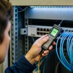
A telecom carrier buying a carrier-grade SFP is not just checking whether it lights up. They are evaluating whether the module behaves predictably under NEBS-style environmental, safety, and electromagnetic stress. This article helps network engineers, transceiver buyers, and field technicians map common NEBS expectations to practical SFP selection and installation decisions.
What carriers mean by NEBS compliance for SFP transceivers
NEBS, often referenced in carrier procurement, is less a single “transceiver-only” checklist and more a disciplined set of network equipment requirements covering safety, reliability, and electromagnetic compatibility. In the field, buyers translate that into test evidence: documentation packages, risk controls for thermal behavior, and EMC performance that won’t destabilize adjacent shelves. For carrier-grade SFP programs, the key is that the transceiver must integrate cleanly with a specific platform and not create noise, latch-up events, or intermittent link failures under vibration and temperature cycling.
Practitioners usually see NEBS requirements paired with telecom-grade standards and test regimes. For electrical and optical interfaces, the carrier expects behavior aligned with Ethernet standards (for example, IEEE 802.3 link optics and electrical characteristics) while also meeting safety and EMC expectations. For authority, review [Source: ETSI NEBS-related guidance] and [Source: Telcordia NEBS requirements as published in GR-series documents], plus vendor-specific compliance statements in datasheets and engineering notices. ETSI Telcordia/NEBS information portals
How to interpret “evidence” rather than marketing claims
In carrier RFPs, compliance is often proven through test reports, conformity declarations, and a documented design margin. A technician will care whether the module’s thermal design supports worst-case chassis airflow and whether the supplier provides traceable component lots. If you cannot obtain test evidence for your exact module part number and DOM/firmware state (where applicable), you should treat “NEBS compliant” as incomplete. For carrier-grade SFP, the most actionable artifacts are: a compliance letter for safety/EMC, an environmental qualification summary, and a platform compatibility note.
Pro Tip: In many carrier environments, the real NEBS risk is not the optics themselves but the module’s interaction with the host’s power integrity and grounding scheme. During shelf bring-up, engineers often discover that a “passes in the lab” transceiver fails intermittently when the host’s ground impedance and cable routing differ from the test setup.
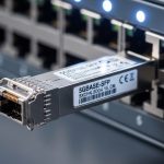
Carrier-grade SFP technical specs that map to NEBS expectations
NEBS-oriented procurement forces you to think beyond wavelength and reach. Carriers stress repeatability: stable optical output, predictable receiver sensitivity, and controlled transmitter power under temperature. They also care about power consumption and thermal headroom, because overheating can shift laser bias currents and degrade link margins. When you select a carrier-grade SFP, you should treat the module’s optical budget and electrical interface as part of the compliance story.
Key optical and electrical parameters carriers scrutinize
Most carrier qualification focuses on: nominal wavelength, link reach at a defined BER target, transmitter power and extinction ratio, receiver sensitivity, and tolerance to temperature. On the electrical side, the host expects correct signal levels, low jitter, and compatibility with the module’s digital diagnostic interface (commonly I2C via SFF-8472 for many SFPs). For high-speed Ethernet optics, ensure the transceiver aligns with relevant IEEE physical layer expectations and the SFP form factor specifications.
Representative comparison table (10G SFP+ multimode and single-mode)
The table below shows typical parameters you would compare when building a compliance-ready bill of materials. Exact values vary by vendor and part number, so always verify against the module datasheet you plan to deploy.
| Module example | Data rate / Form | Wavelength | Typical reach | Connector | Tx power / Rx sensitivity (typ.) | DOM | Operating temp |
|---|---|---|---|---|---|---|---|
| Cisco SFP-10G-SR | 10GBase-SR / SFP+ | 850 nm | ~300 m (OM3), ~400 m (OM4) | LC | Tx higher, Rx sensitivity set for BER | Yes (SFF-8472) | Typically extended commercial |
| Finisar FTLX8571D3BCL | 10GBase-LR / SFP+ | 1310 nm | ~10 km | LC | Tx power and Rx sensitivity engineered for link budget | Yes | Extended temp class options |
| FS.com SFP-10GSR-85 | 10GBase-SR / SFP+ | 850 nm | ~300 m class (depends on fiber) | LC | Vendor-defined optical budget targets | Varies by SKU | Commonly -5 to 70 C or similar |
In NEBS-oriented deployments, you should confirm that the module supports the host’s full temperature and airflow envelope and that the supplier offers an environmental qualification summary for that exact SKU. Even if two modules share the same wavelength and nominal reach, their thermal derating curves and transmitter power control can differ, which affects worst-case link margin.
Deployment scenario: building a NEBS-aligned link in a leaf-spine fabric
Consider a three-tier data center with leaf-spine switching. You deploy 48-port 10G ToR switches at the access layer and 100G uplinks at the aggregation layer, but you still use 10G SFP+ for server connections. In one rollout, a carrier operator installed 600 SFP+ modules across two rooms, with each room targeting 35 C average and up to 50 C hot spots near the top of rack. Fiber runs were 120 m to 220 m on OM4 inside the room, with patch panels and structured grounding.
During acceptance, the carrier’s test script focused on stability under thermal cycling and EMC stress while monitoring link flaps and optical thresholds via DOM. Engineers set alarms for module temperature and optical power drift, then compared those to the expected ranges from the datasheets. The links that were most sensitive to failure were not the farthest ones; they were the ones with marginal optical budgets combined with tighter power supply ripple and a less robust ground bond. That is why carrier-grade SFP selection must include electrical and mechanical integration evidence, not just optical reach.

Decision checklist: selecting a carrier-grade SFP that fits NEBS procurement
Engineers usually make the decision in layers. You start with physical and link compatibility, then you validate environmental and compliance evidence, then you reduce integration risk. Use this ordered checklist when aligning to carrier NEBS requirements and host behavior.
- Distance and fiber type: confirm OM3/OM4 specs, patch panel losses, and connector insertion loss; for single-mode, confirm end-to-end loss including splices.
- Optical budget margin: verify transmitter power and receiver sensitivity at worst-case temperature; ensure margin remains after aging assumptions if required by the carrier.
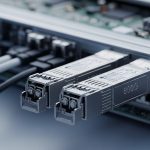
- Switch compatibility: confirm the host switch model’s supported transceiver list and any known interoperability notes; verify module form factor and cage design.
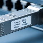
- DOM and diagnostics support: ensure the platform reads standard diagnostic registers (commonly SFF-8472) and that thresholds match operational practice.
- Operating temperature and airflow fit: pick an extended temperature class if the shelf can hit hot spots above typical commercial ranges; validate thermal design assumptions.
- NEBS-related documentation: request compliance letters, test reports, and environmental qualification summaries tied to the exact part number.
- Power and EMC interaction risk: check host power integrity specs and grounding practices; plan cable routing and bonding consistent with carrier standards.
- Vendor lock-in and supply continuity: assess lead times, end-of-life policy, and whether your procurement can support replacements without requalification.
Compatibility caveats that matter
Two SFP+ modules can be “electrically compatible” yet behave differently due to timing, power-on sequencing, or DOM reporting. Some hosts enforce strict thresholds or require specific diagnostic behavior. If your carrier has a strict NEBS evidence bundle, third-party modules may need additional documentation and sometimes platform validation testing to avoid rework.
Pro Tip: When carriers ask for NEBS compliance, they often expect you to verify not only the module’s qualification but also the complete “transceiver plus host plus backplane plus airflow” system. Plan at least a small pilot test that monitors DOM temperature and optical power across the same shelf positions used in production.
Common mistakes and troubleshooting tips in field NEBS rollouts
Even well-selected optics can fail during bring-up if integration details are ignored. Below are concrete pitfalls seen during telecom deployments, along with root causes and practical fixes.
Link flaps that correlate with thermal hot spots
Root cause: the module’s operating temperature is exceeded locally due to airflow obstruction or blocked vents, shifting laser bias and reducing receiver margin. The symptom appears as intermittent link down events during heat soak. Solution: measure actual inlet/outlet airflow and module cage temperatures; reroute cables to restore airflow; consider an extended temperature carrier-grade SFP variant and re-check optical budget with worst-case derating.
DOM alarms for optical power drift without obvious link errors
Root cause: mismatch between expected DOM thresholding and the carrier’s monitoring logic, or DOM readings reflect a different scaling/interpretation than the scripts assume. Another cause is connector contamination causing gradual attenuation increase. Solution: validate DOM register interpretation against the vendor documentation; clean LC connectors and inspect with an optical scope; compare measured optical power against datasheet typical ranges at the module’s current temperature.
EMC-related instability after adding adjacent modules or changing cable routing
Root cause: grounding impedance and cable shield termination can change conducted/radiated noise coupling into sensitive analog sections. This can trigger receiver errors or transmitter power control issues. Solution: ensure chassis bonding straps are intact, follow the carrier’s grounding and cable management practices, and rerun the link stability test while varying only routing and bonding to isolate the coupling path.
“Passes in the lab” but fails after field patch panel changes
Root cause: field patch panels introduce additional insertion loss, micro-bend sensitivity, or connector variability. The optical budget margin may be too tight for real-world aging and connector cleanliness. Solution: recalculate end-to-end loss using measured OTDR or insertion loss results; enforce connector inspection and cleaning procedures; select modules with more margin or reduce path loss by optimizing patching.

Cost and ROI: balancing OEM, third-party, and qualification effort
Pricing for carrier-grade SFP modules varies widely by wavelength, reach, temperature class, and documentation depth. In many markets, OEM-branded 10G optics can range from roughly USD 80 to 250 per module, while third-party equivalents may be USD 30 to 120 depending on supply volume and whether DOM behavior and compliance documentation are fully provided. The ROI decision is rarely just purchase price; it includes requalification time, spare provisioning, and expected failure rates.
From a TCO view, carriers often prefer suppliers that provide consistent lot-to-lot performance and clear end-of-life plans. If a third-party module lacks the NEBS-related documentation bundle or requires additional host validation, the engineering and downtime cost can erase the per-unit savings. A practical approach is to run a limited pilot batch in the same shelf topology, then expand only after measured link stability and DOM threshold behavior match expectations.
FAQ: carrier-grade SFP and NEBS compliance questions engineers ask
What documents should I request for NEBS-related approval?
Ask for compliance letters and test evidence tied to the exact module part number, including safety and EMC statements plus environmental qualification summaries. If your carrier provides a specific NEBS test mapping, request a response that explicitly links the module to those expectations. Also ask for any platform compatibility notes for your switch model.
Do all SFPs support DOM, and does DOM matter for compliance?
Many SFP and SFP+ modules provide digital diagnostics via standard interfaces, enabling monitoring of temperature and optical power. DOM itself is not a NEBS test, but in practice it is essential for proving stable operation during environmental stress and for detecting early degradation. Ensure your host reads DOM correctly and that monitoring thresholds are aligned with vendor guidance.
How do I verify optical margin for NEBS-like worst-case conditions?
Use the datasheet optical budget numbers and apply worst-case temperature and aging assumptions if required. Then incorporate measured link loss from patch panels and connectors, ideally using OTDR for single-mode and insertion loss testing for multimode. If margin is thin, intermittent failures under thermal stress are more likely.
Are third-party carrier-grade SFP modules acceptable?
They can be acceptable if the supplier provides complete documentation and you validate interoperability on the specific host platform. The biggest risk is not basic optical function but mismatch in power-on behavior, DOM interpretation, or environmental performance. Plan a pilot and require evidence that supports your carrier’s NEBS procurement process.
What are the most common causes of SFP failures in hot telecom rooms?
The most common causes include thermal overstress, connector contamination, and insufficient optical budget margin. EMC and grounding issues can also contribute to intermittent errors after changes in shelf configuration. Mitigate by enforcing airflow paths, implementing strict cleaning procedures, and using DOM-based alarms with actionable thresholds.
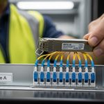
How many modules should I test before full rollout?
A common field approach is to test a small pilot across multiple shelf positions that represent worst-case airflow and cable routing. Many teams start with 5 to 10 modules per transceiver SKU per room, then scale after stability metrics meet acceptance criteria. The exact count depends on your carrier’s risk tolerance and the criticality of the links.
Choosing a carrier-grade SFP for NEBS-aligned networks requires evidence-driven selection: optical margin, thermal fit, host compatibility, and documentation that matches carrier procurement expectations. Next, review carrier transceiver compatibility and interoperability to reduce integration surprises during shelf bring-up.
Expert author bio: Field engineer with hands-on experience deploying 10G and 100G optical interconnects in NEBS-focused telecom environments, including DOM telemetry monitoring and shelf-level troubleshooting. Technical writer who translates vendor datasheets and standards into operational checklists for data center and carrier networks.