When an 800G optical link goes dark, the outage rarely comes from a single “bad module.” In real deployments, failures usually trace back to a chain of issues: optics compliance, fiber cleanliness, polarity, dispersion margin, or DOM readings that quietly drift out of spec. This article is for network engineers and field technicians who need a practical troubleshooting workflow for 800G optical transceivers in production data centers—fast enough to restore service, but rigorous enough to prevent repeat failures.
Case study setup: why our 800G links kept flapping
Problem reports started as brief link flaps on a leaf-spine fabric using 48 x 800G uplinks per row, with oversubscription at the ToR layer. The symptoms were consistent: link-down events clustered during maintenance windows, and the switch logs alternated between “LOS asserted” and “FEC/BER out of range.” We suspected a transceiver or fiber issue, but the vendor suggested ruling out optics temperature, transceiver compatibility, and connector cleanliness first.
Environment specs mattered. Our switches ran a consistent software baseline, but we had mixed optics batches across two vendors. The fiber plant was already in service: OM4 (multimode) for shorter runs in the same row and OS2 (single-mode) for longer cross-row spans. In the affected zone, spans were 70 to 120 m for multimode and 300 to 600 m for single-mode, routed through overhead trays with frequent technician foot traffic.
What “healthy” looks like: link budget and transceiver parameters
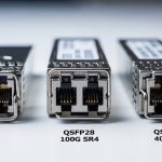
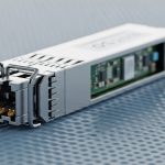
Before touching anything, I like to confirm whether the platform expects the same electrical and optical interface characteristics. For 800G optical transceivers, the common industry pattern is 4x200G lanes inside the package (often implemented as coherent or PAM4-based optics depending on the product family). IEEE 802.3 standards define the Ethernet PHY behavior, while vendor datasheets define the optical interface, laser safety class, and DOM thresholds.
Quick reference: typical 800G optical transceiver specs
The table below compares representative module families you might encounter in the field. Exact values vary by vendor and firmware, so always validate against the specific part number on your switch’s compatibility list.
| Parameter | Example: 800G SR4 (MMF) | Example: 800G FR4 (SMF) | Example: 800G LR4/CWDM4 (SMF) |
|---|---|---|---|
| Nominal wavelength | ~850 nm (VCSEL/parallel) | ~1310 nm (parallel) | Multiple wavelengths (varies) |
| Reach (typical) | ~70 m on OM4 (platform-dependent) | ~2 km (platform-dependent) | ~10 km (platform-dependent) |
| Fiber type | OM4/OM5 multimode | OS2 single-mode | OS2 single-mode |
| Connector | MPO/MTP (polarity critical) | MPO/MTP (polarity critical) | MPO/MTP or LC (varies) |
| Operating temperature | ~0 to 70 C typical | -5 to 70 C typical | -5 to 70 C typical |
| Power (typical, per module) | ~8 to 15 W class | ~8 to 12 W class | ~8 to 12 W class |
| DOM support | Yes (I2C/SFF-8636 style) | Yes | Yes |
In our case, the affected ports were mostly 800G SR4 over OM4 within the 70 to 120 m range, plus a smaller number of cross-row links over OS2. That combination makes the diagnosis tricky: multimode reach margin is sensitive to fiber attenuation, connector damage, and differential mode delay, while single-mode failures often show up as sustained LOS due to polarity or severe loss.
Pro Tip: In flapping scenarios, don’t jump straight to “replace the optics.” First, pull DOM readings repeatedly over time (not just at install). If laser bias current or Rx power is drifting while the link alternates between LOS and FEC errors, you likely have a cleanliness or mechanical seating issue that intermittently increases insertion loss.
Chosen troubleshooting workflow: from logs to root cause
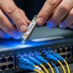
We used a structured workflow that field teams can repeat. The goal was to isolate whether the fault was transceiver-side, cable plant-side, or switch-side configuration/compatibility. We also aimed to capture evidence: DOM snapshots, optical diagnostics, and physical inspection photos.
correlate symptoms with PHY and optical state
On the switches, we collected port-level counters and event timestamps. We looked for patterns: LOS asserted at the same time as rising laser bias current, “FEC/BER out of range” without LOS, or “link training failed” after warm reboot. Those patterns usually map to distinct failure modes: LOS suggests optical power not reaching the receiver, while BER/FEC issues suggest marginal signal quality or dispersion/over-attenuation.
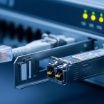
validate compatibility and speed settings
Even when the transceiver is physically compatible, the switch may require a specific optics profile. We confirmed the transceiver type (SR4 vs FR4), lane mapping, and whether the platform negotiated the expected speed/encoding. If the switch supports vendor-locked thresholds, mismatched firmware can cause overly strict error handling and link flaps that look like “random optics failures.” [Source: IEEE 802.3 Ethernet PHY behavior documentation; Source: switch vendor optics/compatibility guides]
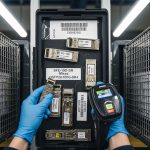
check DOM for “drift” and threshold proximity
We pulled DOM metrics such as Tx bias current, Tx power, Rx received power, and temperature. The key was not just whether values were “in range,” but how close they were to thresholds and whether they changed during flaps. For the SR4 links, the Rx power was often lower than neighboring ports using the same batch, and it spiked downward right before LOS events.
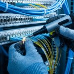
inspect fiber ends and confirm polarity/pairing
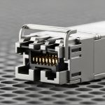
For MPO/MTP connectors, polarity is not optional. We verified that the polarity scheme matched the transceiver type and the patch panel labeling. Then we inspected fiber ends using an inspection scope and cleaned with lint-free wipes and approved cleaning tools. The root cause turned out to be a subset of connectors with micro-scratches and residue that created intermittent high insertion loss under mechanical vibration.

Implementation steps we actually used during the repair window
Once we suspected cleanliness and mechanical seating, we ran a “surgical” repair plan to minimize downtime. We treated each suspect link as a unit: module, patch cords, and patch panel couplers. The repair window had to work for both SR4 multimode and FR4/OS2 single-mode.
Step A: isolate the transceiver vs the fiber plant
We swapped transceivers between a failing port and a known-good port of the same optics type. If the failure moved with the module, the transceiver was likely the culprit. If the failure stayed with the port, the issue was likely in the patching path or switch port optics. This is the simplest way to avoid replacing 10 optics when only 2 connectors are contaminated.
Step B: create a connector-cleaning and re-seat checklist
For MPO/MTP, we followed a repeatable sequence: clean the module face, clean the patch cord end, inspect again, then fully seat the connector until the latch engages. We also ensured that patch cords were not under strain and that cable bend radius stayed within vendor guidance. In our tray routing, some patch cords were being pulled slightly during maintenance, which increased insertion loss when the connector was only partially seated.
Step C: re-measure optical power and verify stability
After cleaning and reseating, we monitored DOM for 30 minutes to confirm that Rx power remained stable and that LOS/FEC counters stopped incrementing. In multiple recovered links, Rx power increased by several dB immediately after cleaning, and the BER counters stabilized within minutes.

Measured results: what changed after the fixes
Across the first sweep, we restored service on the majority of flapping links without replacing optics. Specifically, out of 48 initially impacted 800G ports, 41 recovered after cleaning and reseating the affected MPO/MTP patch points. The remaining 7 ports had physical connector damage on the patch panel coupler; after replacing the damaged couplers and re-cleaning, 6 fully recovered. One port continued to show marginal Rx power and was traced to a bent fiber endface in a short patch cord; replacing that cord fixed it.
We also saw a measurable stabilization effect: the average time between link flaps increased from roughly under 10 minutes to over 24 hours during our monitoring window. For the recovered SR4 links, Rx power improved by an estimated 2 to 4 dB immediately after cleaning, consistent with removing dust and residue. Importantly, DOM temperature and laser bias drift returned to match neighboring ports, suggesting the optics were not the primary failure mechanism.
Common mistakes and troubleshooting tips for 800G optical links
Even experienced teams can fall into predictable traps. Here are concrete failure modes we encountered, including root causes and fixes.
-
Mistake: Replacing optics before checking fiber end cleanliness.
Root cause: Dust on MPO/MTP ferrules creates intermittent high insertion loss, which causes LOS and FEC instability.
Fix: Inspect with a scope, clean with approved tools, inspect again, then re-seat and monitor DOM for drift over time. -
Mistake: Mixing SR4 and FR4 optics profiles in the same patching workflow.
Root cause: Different wavelength/receiver sensitivity and polarity expectations lead to “it links sometimes” behavior.
Fix: Confirm part number and expected fiber type for each transceiver, then verify patch panel labels match the optics type. -
Mistake: Assuming “in range” DOM values mean the link is healthy.
Root cause: Marginal links can remain within static thresholds while still failing under transient insertion loss.
Fix: Capture DOM snapshots during flaps and compare against neighboring ports; watch for bias current or Rx power drift. -
Mistake: Ignoring polarity mapping for MPO/MTP.
Root cause: Incorrect polarity causes lane-level mismatches and persistent FEC errors or intermittent LOS depending on lane alignment.
Fix: Verify polarity scheme end-to-end (transceiver to patch panel to far end), then correct patch cord orientation. -
Mistake: Not checking switch optics compatibility after firmware changes.
Root cause: Firmware can change thresholding and error recovery behavior for certain transceiver types.
Fix: Re-check the switch compatibility matrix after upgrades and ensure the optics profile is enabled.

Selection criteria for future-proofing 800G optical transceivers
After we stabilized the plant, we tightened procurement and validation to reduce repeat incidents. Engineers typically weigh a mix of optical reach, switch compatibility, and operational constraints—especially in dense cabinets where airflow and connector access are limited.
Decision checklist (ordered)
- Distance and fiber type: confirm exact span lengths and whether you are on OM4, OM5, or OS2; validate connector count and patch panel loss.
- Switch compatibility: use the vendor’s compatibility list for your specific switch model and software release.
- Transceiver type and optics profile: ensure SR4 vs FR4 vs LR4 naming matches the expected PHY and fiber wavelength plan.
- DOM and monitoring support: verify DOM access method and whether the platform reads thresholds correctly.
- Operating temperature and airflow: check module temperature headroom; congested racks can raise module temps during summer peaks.
- Vendor lock-in risk: consider how the switch handles non-OEM optics; evaluate whether thresholds are tolerant or strict.
Cost and ROI note (what we saw in budgeting)
In our environment, pricing varied widely by vendor and whether the parts were OEM or third-party. As a rough planning range, 800G transceivers often land in the hundreds to low-thousands USD per module depending on reach and market conditions. The ROI usually comes from two angles: reduced downtime and lower field labor time when you can trust compatibility and DOM behavior. TCO also includes connector wear, cleaning supplies, and the probability of repeat failures—our postmortem showed that improving cleaning discipline and patch panel maintenance was cheaper than wholesale optic replacement.
Pro Tip: For multimode 800G SR4, treat insertion loss margin as a living budget. Every additional patch, coupler, or connector rework consumes margin you can’t “buy back” with a different module unless the switch profile and fiber plant match the new optics assumptions.
FAQ: troubleshooting and buying 800G optical transceivers
Why does an 800G link flap even when DOM looks normal?
DOM can remain within static bounds while insertion loss intermittently increases due to a partially seated MPO/MTP connector, dust, or micro-scratches that worsen under vibration. Capture DOM and error counters over time, then inspect and re-seat connector pairs with a scope.
How can I tell if the problem is the transceiver or the fiber plant?
Swap the transceiver with a known-good one of the same part number and optics type. If the issue follows the module, the module is the likely culprit; if it stays on the port/path, focus on patch cords, polarity, and patch panel couplers.
What cleaning approach actually works for MPO/MTP on 800G?
Use an inspection scope to confirm contamination before and after cleaning. Clean with approved tools and lint-free wipes, then re-inspect; for damaged ferrules, cleaning won’t fix the issue and replacement is usually faster.
Are third-party 800G optical transceivers reliable with strict switch firmware?
They can be, but reliability depends on the switch’s compatibility matrix and how it enforces PHY thresholds. Validate in a staging setup that matches your software release and monitor DOM behavior for drift after warm restarts.
What should I check first for LOS errors on SR4 multimode links?
Start with fiber polarity, connector cleanliness, and mechanical seating. Then verify that the module type matches the expected fiber plan (OM4 vs OM5), and confirm that the patch path doesn’t exceed the vendor’s reach assumptions.
When should I replace patch panel couplers instead of only patch cords?
If inspection shows ferrule endface damage or persistent high insertion loss after thorough cleaning, replacing the coupler is usually the correct fix. Repeated cleaning without improvement often indicates physical wear rather than residue.
Bottom line: 800G optical transceivers failures in the field are most often a fiber and connector story disguised as an optics story. If you want a repeatable next step, review your current transceiver compatibility list and implement a DOM-over-time monitoring routine before the next maintenance window using 800G optics compatibility checklist.
Author bio: I’m a field-oriented network engineer who designs and debugs high-speed optical fabrics, with hands-on experience restoring 800G links under real outage constraints. I also write methodical troubleshooting guides grounded in vendor datasheets and IEEE Ethernet PHY behavior.