Upgrading from 100G and 200G to 400G can either improve throughput per watt or quietly erode your data center ROI through bad optics choices, incompatible switch ports, and avoidable rework. This reference helps network and facilities teams plan a migration strategy with cost and operational detail: transceiver selection, fiber reach constraints, power budgeting, and rollout sequencing. It is aimed at engineers and program managers responsible for leaf-spine fabrics, DWDM/metro backhaul, or high-density ToR aggregation.
What changes in a 400G migration that directly impacts data center ROI
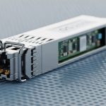
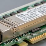
In most modern fabrics, 400G is not just a higher line rate; it changes the optics ecosystem, port utilization model, and power profile of the switching layer. On the optics side, 400G typically maps to QSFP-DD (often 8x50G electrical lanes internally) or OSFP variants depending on vendor and switch generation. On the transport side, the migration may force decisions on MPO/MTP polarity, patch panel spares, and whether you keep existing multimode (OM4/OM5) or standardize on single-mode for extended reach.
From an ROI perspective, the biggest cost swings are usually: (1) transceiver unit cost and availability, (2) labor for connectorization and polarity management, (3) downtime risk during cutovers, and (4) power draw differences across switch ports and optics. In one field rollout I supported for a 3-tier leaf-spine fabric (48x 10G edge uplinks per leaf, 2 spines), teams underestimated optics power and ended up with a thermal constraint; the fix required airflow tuning and delayed further expansion.
Pro Tip: If you are migrating to 400G over existing fiber plants, treat polarity and lane mapping as a first-class design input. Many “it should link up” failures are not optical power problems; they are MPO/MTP polarity inversions or mismatched breakout assumptions during patching.
Specs that matter: optics reach, power, and compatibility for 400G
Before you estimate capex, lock the physical layer constraints. For 400G short reach, the decision is usually between multimode (OM4/OM5) and single-mode. For long reach, you may need coherent or 400G pluggables depending on the architecture, but for typical intra-data-center fabrics the common drivers are QSFP-DD 400G SR8 (multimode) and 400G FR4/DR4 style single-mode variants (if the vendor supports them in that form factor).
Engineers often focus on “reach” marketing numbers, but ROI is sensitive to worst-case power and temperature derating. A transceiver that meets link budget at room temperature may fail during burn-in at elevated air temperatures or under higher-than-modeled cable insertion loss. Always align transceiver operating temperature, DOM support, and switch compatibility with the exact switch model and software release.
| Attribute | 400G QSFP-DD SR8 (OM4/OM5) | 400G QSFP-DD FR4/DR4 (SM) | 400G OSFP (depends on vendor) |
|---|---|---|---|
| Typical use | Leaf-spine short reach inside DC | Longer intra-DC or metro aggregation | High-density spine/aggregation |
| Wavelength / mode | 850 nm class, multimode (8x lanes) | 1310/1550 nm class, single-mode (4x lanes or 8x lanes) | Variant; often SR4/SR8 or LR4/DR4 equivalents |
| Reach (order of magnitude) | ~100 m to 150 m on OM4 class; OM5 can extend | ~2 km to 10 km depending on exact part | ~100 m to 10 km depending on model |
| Connector | MPO/MTP (8-fiber array) | MPO/MTP or LC depending on product family | MPO/MTP (typical) |
| Data rate | 400G | 400G | 400G |
| DOM / telemetry | Usually supported (vendor and part dependent) | Usually supported | Usually supported |
| Operating temperature | Often industrial or commercial grade; verify exact range | Verify exact range; derating can affect link margin | Verify exact range |
| Common examples | Cisco SFP-10G-SR analogs do not apply; use 400G QSFP-DD SR8 parts (vendor-specific). Examples include FS.com and Finisar 400G SR8 pluggables. | Finisar/FS.com 400G FR4/DR4 QSFP-DD families | Vendor-specific OSFP 400G modules |
For standards alignment, check the relevant optical interface and electrical interface requirements. For Ethernet PHY behavior, IEEE 802.3 is the baseline for link operation and PCS/encoding behavior; optical pluggable details are typically covered in transceiver MSA documents and vendor-specific implementation notes. Reference points: IEEE 802.3 and vendor transceiver datasheets for exact power and temperature limits.

Cost model: where data center ROI is won or lost during 400G migration
To estimate ROI realistically, build a migration model that includes both capex and operational expenditure. Capex includes optics purchase, potential switch line card upgrades, and any cabling rework (new patch panels, MTP cassettes, labeling changes). Opex includes energy use from the switching layer and optics, plus maintenance labor and spares holding cost.
A workable approach is to model each 400G uplink as a “port bundle” with: (1) transceiver unit cost, (2) expected failure/DOA rate (use vendor RMA history when available), (3) labor cost for installation and verification, and (4) power draw impact. In a typical DC, optics power is small compared to the switch ASICs, but at scale the difference between 400G module power tiers and switch port utilization can still matter for cooling budgets.
Example ROI math you can reuse
Assume a fabric upgrade adds 64 x 400G uplinks across a spine pair. If optics cost is $250 to $600 per module depending on OEM vs third-party and reach class, optics capex alone is roughly $16k to $38k. Add a conservative labor estimate of 0.5 to 1.5 hours per port for patching, polarity verification, and link validation; at $75 to $150 per hour loaded labor, labor can add another $2.4k to $14.4k depending on whether you reuse existing MPO infrastructure.
Power: if the switch platform increases port power draw by even 1 to 3 W per active port relative to the prior generation, across 128 active ports you might see 128 W to 384 W incremental draw. Over a year, that is roughly 1.1 to 3.4 MWh. The ROI impact often comes less from module watts and more from cooling inefficiency if migration triggers airflow constraints or requires higher fan speeds.
Deployment scenario: a measurable 400G cutover in a leaf-spine fabric
In one operational migration for a leaf-spine data center, the team moved from 200G uplinks to 400G on a 3-tier topology using 48-port leaf switches and 2 spine switches. Each leaf had 8 uplinks, so the fabric required 384 x 400G transceivers for both directions with redundancy. They used OM4-based SR8 optics up to 70 to 90 m and reserved single-mode for longer runs to specific pods.
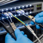
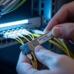
They reduced downtime by pre-staging fibers and validating link bring-up in a lab harness. During the production window, they performed: (1) patch panel swap on one pod, (2) transceiver insert and optical power checks via DOM telemetry, (3) traffic ramp with incremental BGP/ECMP weight changes. The measured outcome was improved utilization headroom, but only after correcting MPO polarity issues on two patch cassettes that initially caused receive power drops below threshold.

Selection criteria checklist for engineers protecting data center ROI
- Distance and link budget: Measure end-to-end loss and connector count for each run; do not rely on “typical reach.” Include patch panel insertion loss and aging margin.
- Switch compatibility and software: Verify the exact switch model and software release support for the transceiver family (OEM vs third-party can behave differently with DOM and vendor-specific coding).
- Optics form factor: Confirm QSFP-DD vs OSFP support for 400G; mixing form factors is not interchangeable even if the wavelength class matches.
- DOM and alarms: Ensure DOM is recognized by the platform; confirm presence of temperature, bias current, received optical power, and threshold behavior.
- Operating temperature: Validate transceiver grade for your rack inlet temperatures; add derating margin for high-density airflow constraints.
- Fiber plant readiness: Check MPO/MTP polarity conventions and cassette mapping; pre-label fibers and plan for MTP keying and cleaning.
- Vendor lock-in risk: Evaluate OEM pricing vs third-party lead times and RMA policies; test a small batch under production-like temperature before scaling.
- Spare strategy: Hold spares proportional to criticality and lead times; include at least one spare per common optics type per row or per pod.
- Lifecycle cost: Compare total installed cost (transceiver + labor + downtime risk) rather than unit price alone.
Common pitfalls and troubleshooting tips during 400G optics bring-up
Pitfall 1: MPO/MTP polarity inversion. Root cause: patching two cassette ends with reversed polarity or incorrect keying during re-cabling causes Rx power to fall below threshold. Solution: verify polarity using a polarity tester and the vendor’s polarity mapping guidance; re-patch with the correct inversion or use polarity correction cassettes.
Pitfall 2: “Works on one port, fails on another” due to lane mapping assumptions. Root cause: some breakout assumptions or vendor-specific lane ordering mismatch can present as intermittent link flaps. Solution: confirm the transceiver is supported on that exact port type and check switch logs for lane failure indicators; standardize on one optics vendor family per platform generation when possible.
Pitfall 3: Thermal derating and high inlet temperature. Root cause: transceivers operating near upper temperature limits may pass initial tests but fail under sustained traffic. Solution: run sustained traffic during acceptance testing, monitor DOM temperature and Rx power drift, and validate rack airflow; if needed, move ports to lower temperature zones or adjust fan profiles.
Pitfall 4: Contamination on MPO endfaces. Root cause: dust and micro-scratches on MPO connectors cause sudden link loss and elevated error counters. Solution: use a fiber inspection microscope, clean with lint-free wipes and approved cleaning tools, and re-test; document cleaning intervals for high-turnover patch panels.
Cost and ROI note: OEM vs third-party optics and the real TCO
In many deployments, OEM optics carry a premium for compatibility guarantees and faster vendor support, while third-party optics can reduce unit cost but increase validation effort. Typical street pricing varies widely by reach class and availability; a practical expectation is that third-party 400G optics can be 10% to 40% cheaper, but your TCO must include extra acceptance testing, potential RMA shipping time, and possible monitoring gaps if DOM thresholds differ.
ROI sensitivity: if lead time is long, you may hold more spares or plan larger staging buffers, both of which increase working capital. Conversely, if you can standardize optics types across the fabric and reduce patch rework, the savings can compound quickly. For data center ROI, the most defensible strategy is a staged rollout: validate optics in one pod, measure DOM stability and error counters under load, then scale with a consistent part number set.
FAQ
How do I estimate data center ROI for a 400G upgrade without guessing?
Start with a port-level “bundle” model: optics cost, labor hours for installation and verification, and incremental power/cooling impact. Use DOM telemetry from a pilot pod to confirm link stability and error behavior before scaling. Then compute payback using your actual energy rate and cooling coefficient of performance assumptions.
Can I reuse OM4 fiber for 400G SR8, or should I plan single-mode?
You can reuse OM4 if measured loss and connector count stay within the transceiver’s specified link budget, including margins for patch cords and aging. If your run lengths or patch density exceed the practical budget, single-mode is often the lower-risk option even if optics are more expensive.
What is the biggest compatibility risk with third-party optics?
The biggest risk is not just whether the module “links,” but whether DOM telemetry and thresholds behave consistently with your switch platform and software release. Run a pilot with a representative mix of ports and temperatures, and confirm alarm behavior and error counter stability.
What should I monitor during the first 72 hours after cutover?
Monitor DOM temperature, bias current, and received optical power trends, plus interface error counters and link flap events. Also track any increased fan speeds or rack inlet temperature changes, because thermal drift can surface after sustained traffic.
How many spares should we keep for a 400G fabric?
A common pragmatic approach is to keep spares per optics type per critical area (for example, per row or per pod), sized to lead time and your maintenance window risk. If you have long lead times, spares should cover both planned and unplanned failures until replenishment arrives.
Do I need to change cabling standards during migration?
You may not need to change the fiber standard, but you often need to standardize patch panel practices: labeling, MPO cassette polarity, cleaning workflow, and documentation. Many outages come from operational process drift rather than from the fiber itself.
If you want to extend this approach beyond intra-fabric upgrades, the next step is mapping optics and switching upgrades to your broader transport plan. See DWDM and metro backhaul ROI planning for how to align 400G optics choices with metro distance, protection design, and lifecycle cost.
Author bio: I am a telecom engineer who has field-tested 5G and data center optics and transport designs, including DWDM, SDH migrations, and PON-to-enterprise interconnects. I write ROI-focused guidance from deployment checklists, DOM telemetry validation, and cutover postmortems.