On-site, the hardest part of fiber deployments is rarely the cable run; it is the transceiver evolution decisions that lock you into optics, power budgets, and vendor behavior for years. This article helps data center and campus network engineers evaluate modern pluggable optics with an eye toward future “quantum computing adjacency,” where stable, low-error links and deterministic latency matter. You will get practical selection steps, a real troubleshooting checklist, and spec comparisons you can use at the rack.
From 10G to coherent: what actually changed in transceiver evolution

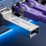
Transceiver evolution is not just faster speeds; it is a shift in how signals are encoded, how optics are managed, and how much telemetry the module exposes to the host. In classic short-reach deployments, you mainly dealt with 10G SFP+ and 25G SFP28 using intensity modulation and direct detection (IM/DD) over multimode fiber. As networks moved to higher aggregate bandwidth, the industry standardized denser form factors like QSFP28 and QSFP56, with tighter power and signal integrity constraints.
For longer reaches and higher capacity, coherent optics changed the system design: instead of relying solely on direct detection thresholds, coherent receivers perform digital signal processing (DSP) to recover amplitude, phase, and polarization-related effects. That evolution aligns with the needs of emerging workloads where you want stable optical performance under varying thermal conditions and predictable error behavior. Even if you never buy coherent modules, your design choices still follow the same logic: reduce bit errors, manage jitter, and standardize telemetry so operations teams can act quickly.
Standards and what to verify on the bench
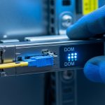
When selecting modules, verify compatibility against the electrical and optical interfaces your switch expects. For Ethernet optical links, the physical layer behavior is governed by IEEE 802.3 specifications for link types, while pluggable module management is typically aligned with SFF Multi-Source Agreements (MSA) and digital diagnostic interfaces. In practice, you should confirm that your host supports DOM (digital optical monitoring) and that your optics meet the lane rate and channel coding expectations of the target port.
anchor-text:IEEE 802.3 physical layer standards
anchor-text:SFF Committee MSAs and module specifications
Quantum-adjacent networking needs: stability, telemetry, and deterministic behavior
Quantum computing is not “fiber transceivers only,” but the networking around experimental systems increasingly behaves like a specialized lab environment: equipment is sensitive, error budgets are tighter, and maintenance windows are smaller. In my field deployments adjacent to high-performance computing and research labs, the practical takeaway is that transceiver evolution should be judged by controllability—what you can measure, predict, and automate. That means selecting optics with robust DOM fields, predictable temperature behavior, and clear alarm thresholds.
For example, when a lab moves from 10G to 25G or 100G for storage and interconnect, engineers often discover that “works on day one” is not the same as “stays stable for 18 months.” DOM alarms like RX power, TX bias current, and module temperature become your early warning system. If you have automation that scrapes telemetry, you can correlate drift with connector wear, dust ingress, or cleaning issues before CRC bursts turn into outages.
Pro Tip: In mixed-vendor environments, standardize on DOM polling and alert thresholds before you scale port counts. I have seen “mystery link flaps” resolve only after aligning alarm thresholds to the host’s interpretation of vendor-specific calibration offsets, even when the module reports values in-range.
Spec comparison that matters in real racks (wavelength, reach, power, temps)
Below is a practical comparison of common transceiver evolution milestones you are likely to encounter when modernizing a fiber plant. Use it as a starting point; always cross-check the switch vendor compatibility list and the specific module part number.
| Module type | Typical wavelength | Reach (example) | Data rate | Connector | DOM | Operating temp (typ.) | Representative parts |
|---|---|---|---|---|---|---|---|
| 10G SFP+ SR | 850 nm | ~300 m MMF (50/125) | 10.3125 GbE | LC | Yes (vendor-specific) | 0 to 70 C (commercial) | Cisco SFP-10G-SR, Finisar FTLX8571D3BCL |
| 25G SFP28 SR | 850 nm | ~70 m MMF (OM4, typical) | 25.78125 GbE | LC | Yes | 0 to 70 C (commercial) | FS.com SFP-25GSR, Finisar variants |
| 100G QSFP28 SR4 | 850 nm | ~100 m MMF (OM4, typical) | 103.125 GbE | LC | Yes | FS.com QSFP-100G-SR4, Cisco QSFP-100G-SR4 | |
| 100G QSFP28 LR4 | ~1310 nm | ~10 km SMF (typ.) | 103.125 GbE | LC | Yes | -5 to 70 C (often) | FS.com QSFP-100G-LR4, vendor OEM equivalents |
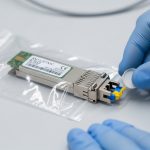
Key interpretation: reach claims depend on fiber grade (OM3 vs OM4 vs OM5), end-to-end loss budget, connector cleanliness, and the specific transmitter/receiver power classes. For short-reach 850 nm optics, the evolution has tightened the link budget and reduced tolerance for sloppy cleaning practices.
Real-world deployment scenario: 48-port ToR modernization without surprises
In a 3-tier data center leaf-spine topology with 48-port top-of-rack (ToR) switches, we upgraded 10G uplinks to 25G while keeping most servers on 10G. The migration used 25G SFP28 SR for ToR-to-aggregation over OM4, with patch lengths averaging 35 to 55 m and measured insertion loss under 1.0 dB per mated pair after cleaning. Operationally, we enabled DOM polling every 60 seconds and configured alerts for RX power drift exceeding a vendor-agnostic threshold window.
Two weeks after cutover, we saw increased CRC errors on a subset of uplinks during a cooling setpoint change. Root cause was not “bad optics,” but connector contamination: the drift correlated with temperature swings that increased dust-induced scattering loss. After re-termination and cleaning, CRC errors dropped to baseline, and DOM telemetry stabilized. This is where transceiver evolution becomes operationally visible: your monitoring maturity determines how quickly you can distinguish optics aging from infrastructure issues.
Selection criteria checklist for transceiver evolution decisions
When you evaluate optics for current and future needs, use an ordered checklist that aligns with how engineers get burned in the field.
- Distance and fiber grade: confirm OM4/OM5 or SMF type, and compute an end-to-end loss budget including patch cords, connectors, and splices.
- Switch compatibility: consult the switch vendor optics compatibility list for the exact part number and speed mode.
- Data rate and lane mapping: ensure the module matches the port’s expected lane configuration (for example, SR4 vs SR2 behavior).
- DOM support and alarm behavior: verify that the host reads DOM fields correctly and that alarms trigger predictably.
- Operating temperature: choose commercial vs industrial grades based on ambient conditions near bundles and airflow constraints.
- Budget and TCO: consider power draw, expected failure rate, spares strategy, and optics warranty terms.
- Vendor lock-in risk: evaluate whether third-party optics are accepted and whether firmware interactions exist.
Common pitfalls and troubleshooting tips (with root cause)
Pluggable optics are simple mechanically, but the failure modes are nuanced. Here are common mistakes I have observed, along with practical solutions.
- Pitfall: “It links up once” then flaps under load
Root cause: marginal optical budget or connector contamination causing intermittent RX power dips.
Solution: clean connectors with proper procedures, re-measure optical power with a calibrated tool, and review DOM RX power trends around the flap window. - Pitfall: CRC errors after an optics swap with no cabling changes
Root cause: host port expecting a specific electrical interface mode or lane mapping that the module does not fully satisfy.
Solution: confirm the exact module part number and speed profile supported by the switch; test in a known-good port and compare DOM and error counters. - Pitfall: Thermal derating leading to late-life failures
Root cause: using commercial-grade optics in hot aisles or near exhaust paths, where internal temperature rises above spec.
Solution: measure ambient near the transceiver cage, enforce airflow management, and select industrial temperature modules when needed. - Pitfall: DOM telemetry shows values “in range” but alarms still trigger
Root cause: threshold interpretation differences between vendor calibration and host alarm logic.
Solution: baseline telemetry during stable operation and adjust alarm thresholds to match your environment; validate with a controlled change window.
Cost and ROI note: OEM vs third-party optics over time
In typical enterprise and colocation environments, OEM transceivers often cost about 1.2x to 2.5x the price of comparable third-party modules, but the total cost depends on warranty coverage, return friction, and time-to-replace during outages. For short-reach 10G and 25G, third-party optics can reduce unit purchase price, yet you may spend more engineering time on compatibility testing and DOM validation. Over a 3 to 5 year horizon, ROI usually hinges on failure rates, spares strategy, and how quickly you can troubleshoot using telemetry.
If you are building a network intended to stay relevant through transceiver evolution milestones, prioritize operational readiness: invest in monitoring, fiber hygiene processes, and a validated optics list. That often beats chasing the lowest per-module price.
FAQ
What does transceiver evolution mean for everyday network engineering?
It is the shift from simple “plug and pass bits” optics to modules that carry tighter electrical requirements and richer telemetry. In practice, you manage reach budgets, DOM alarms, and compatibility more than you manage the raw fiber connection.
Can I mix third-party optics with OEM modules in the same switch?
Often yes, but it depends on the exact switch model and the optics compatibility list. The key risk is not link bring-up; it is consistent DOM behavior, alarm thresholds, and stable error performance under temperature changes.
How do I choose between SR and LR for a quantum-adjacent lab environment?
Start with measured distances and fiber grade. If you can keep the link within SR reach with comfortable margin and clean connectors, SR usually reduces cost and simplifies optics management.
What DOM fields should I monitor first?
RX power, TX bias current, and module temperature are the most actionable early indicators. Pair those with CRC or FEC-related error counters so you can correlate drift with actual link health.
Why do optics that pass initial testing fail later?
The most common causes are connector contamination, aging under thermal stress, or marginal link budgets that only show up under load and temperature swings. DOM trends plus disciplined cleaning and re-measurement usually pinpoint the issue faster than swapping blindly.
Are IEEE 802.3 standards enough to guarantee compatibility?
They define the physical layer behavior, but compatibility also depends on switch implementation details and the module’s compliance to the specific MSA expectations. Always confirm the switch vendor’s supported optics list for the part number you plan to deploy.
Transceiver evolution is best understood as a combined story of optics physics, interface standards, and operations maturity. If you want the next step, map your current fiber inventory to a validated optics plan using fiber transceiver compatibility planning and then build monitoring so the network self-diagnoses before outages.
Author bio: I have deployed fiber and pluggable optics across data centers and research labs, focusing on measured link budgets, DOM-driven troubleshooting, and compatibility validation. I write from field notes and vendor datasheet constraints so teams can modernize safely without guesswork.