In a smart factory, one bad link can stop a production line: machine vision stutters, PLC communications jitter, and alerts pile up. This article helps operations, OT engineers, and network teams select smart factory optics that deliver stable bandwidth and predictable latency over fiber. You will see real-world deployment numbers, an engineer-style selection checklist, and common failure modes to avoid.
Why smart factory optics matter in OT networks
Most industrial automation traffic is sensitive to link stability and deterministic behavior. Optical transceivers support high bandwidth per port, low EMI, and long reach compared with copper, which reduces rework when plants expand. For example, IEEE 802.3 Ethernet PHYs rely on clean optical power and correct connector geometry; if a transceiver or fiber run is marginal, you can see CRC errors, link flaps, and degraded throughput even when the link “comes up.” [Source: IEEE 802.3 (Ethernet Physical Layer specifications)]
In practice, smart factory optics often sit at the boundary between plant-floor switches and machine cells. Common use cases include uplinks from 10G/25G ToR switches to aggregation, and fiber runs to vision systems or industrial PCs. When you align wavelength, reach, and connector type, you reduce downtime and improve maintainability during scheduled production windows.
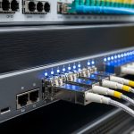
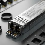
[[IMAGE:Close-up product photography of two pluggable SFP-10G SR transceivers inserted into a rugged industrial Ethernet switch port, macro lens, shallow depth of field, cool blue factory lighting, visible fiber patch cables with LC connectors, realistic textures, high detail, 4k]

Core specs to match: wavelength, reach, power, and temperature
Engineers usually choose optics by data rate and distance first, then verify optical budget and environmental limits. For short-to-mid reach in plants, multimode 850 nm (MMF) is common; for longer runs or higher stability, single-mode 1310/1550 nm is typical. Always confirm that the switch vendor supports the transceiver type (SFP/SFP+/SFP28/QSFP), because compatibility policies vary by platform and firmware.
| Spec | Typical MMF (850 nm) | Typical SMF (1310 nm) | Example part numbers |
|---|---|---|---|
| Data rate | 10G, 25G | 10G, 25G | Cisco SFP-10G-SR; Finisar FTLX8571D3BCL; FS.com SFP-10GSR-85 |
| Wavelength | 850 nm | 1310 nm | 850 nm SR; 1310 nm LR/ER |
| Reach (typical) | 300 m (10G, OM3/OM4); up to ~400 m with OM4 | 2 km (10G LR class) or more depending on optic | 10G SR; 10G LR |
| Connector | LC (most common) | LC (most common) | LC duplex |
| Form factor | SFP / SFP+ / SFP28 | SFP / SFP+ / SFP28 | SFP-10G-SR; SFP28 variants |
| Operating temperature | Usually commercial or industrial grades | Same selection rule | Industrial optics often rated to -40 to 85 C |
| Power/diagnostics | DMI/DOM support varies | DMI/DOM support varies | Verify DOM page in vendor docs |
Look beyond reach. You must validate optical power levels, receiver sensitivity, and link loss budget for your specific fiber type (OM3, OM4, OS2), splice count, and patch panel aging. Vendor datasheets and switch transceiver compatibility matrices are the fastest path to correct selection. [Source: Cisco transceiver compatibility documentation; vendor transceiver datasheets]
Pro Tip: If you see intermittent CRC errors after a line expansion, measure total link loss including patch panels and connectors, not just cable length. “Short” runs can still fail when connector cleanliness or remating cycles quietly increase insertion loss.
[[IMAGE:Vector-style concept illustration of an OT network “cell” with labeled light paths from a machine vision camera through a fiber patch panel into an industrial switch, showing wavelength 850 nm and 1310 nm lanes, clean icons, flat design, high contrast, minimal text, infographic clarity]
A real deployment scenario: 10G to vision cells with predictable uptime
Consider a 3-tier data center leaf-spine layout adapted for manufacturing: 48-port 10G ToR switches in each production bay uplink to 10G aggregation over fiber. Each bay serves 12 machine cells running vision and motion control, with average traffic bursts of 3 to 6 Gbps during inspection cycles. Engineers deployed 10G SR optics at the ToR to cell edge for runs of 120 to 220 m on OM4, using LC duplex connectors and industrial-rated transceivers. Over six months, the team reported fewer link flaps because the fiber plant-floor runs were isolated from EMI sources that previously affected copper, and the optics provided stable link training.
When one bay was later extended by 180 m beyond the original tray route, they switched that segment to 10G LR-class single-mode optics to preserve optical margin rather than forcing a marginal MMF budget. This small change avoided production downtime during the next scheduled commissioning window.

Selection criteria checklist engineers actually use
- Distance and fiber type: confirm OM3/OM4 or OS2, then pick wavelength and reach class.
- Switch and port compatibility: verify SFP/SFP+/SFP28/QSFP form factor and vendor support policy.
- Optical budget: include splice loss, patch panel loss, and connector insertion loss; validate receiver sensitivity in the datasheet.
- DOM or DMI support: ensure the transceiver exposes diagnostics (temperature, bias, TX power, RX power) and that your monitoring tool reads them.
- Operating temperature: choose industrial grade for control rooms or cable trays near heat sources; avoid commercial-grade in harsh areas.
- Connector strategy: standardize on LC duplex and maintain labeling to reduce remating errors.
- Vendor lock-in risk: evaluate OEM vs third-party, and test a small batch before scaling to full plant rollouts.
Common pitfalls and troubleshooting in smart factory optics
1) “Link up, but traffic drops”
Root cause: marginal optical power or excessive connector loss causing late errors (CRC/FCS) rather than a hard link failure.
Solution: clean and inspect connectors, re-measure link loss, and compare RX power against the datasheet receiver sensitivity.
2) Frequent link flaps during vibration or remounting
Root cause: connector contamination or poor seating in patch panels; industrial vibration can amplify tiny mechanical misalignments.
Solution: follow IEC-style cleaning procedures, replace suspect patch cords, and ensure latching tabs are fully engaged.
3) Transceiver not recognized or runs in fallback mode
Root cause: platform compatibility limits, missing DOM support, or incorrect transceiver class for the port.
Solution: check the switch compatibility matrix, update switch firmware if supported, and test with a known-good transceiver SKU before mass deployment.
4) Temperature-related degradation
Root cause: using commercial-grade optics in hot cable trays or near drives and heaters.
Solution: move to industrial temperature-rated optics and verify thermal airflow around the switch.

Cost and ROI: OEM vs third-party optics in plant economics
In typical procurement, OEM transceivers might cost roughly $80 to $250 per unit depending on data rate and reach, while reputable third-party options can be lower (often $40 to $150). TCO should include downtime risk, cleaning labor, and the cost of failed spares. If a single production line interruption costs tens of thousands of dollars per hour, the ROI of choosing optics with strong DOM visibility, documented compatibility, and industrial temperature ratings is usually immediate.
Also consider power and cooling: optics themselves are usually small, but stable links reduce retransmissions and CPU load on switches. Over a year, operational savings often come from fewer truck rolls and faster fault isolation using DOM telemetry. [Source: OEM and third-party transceiver datasheets; field practice reports in reputable tech media like Network World]
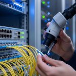
[[IMAGE:Photorealistic lifestyle scene inside a smart factory electrical room, an OT engineer holding a fiber inspection scope while checking LC connectors near an industrial switch rack, warm tungsten lighting mixed with LED panels, safety PPE, realistic depth of field, documentary style, high detail]
FAQ on smart factory optics
Q: Are smart factory optics the same as data center optics?
A: The core technology is similar, but industrial environments demand stricter temperature tolerance, robust connector handling, and better diagnostics. Many buyers prioritize industrial-grade transceivers and DOM support for faster troubleshooting.
Q: Should I use multimode