OPC UA deployments in plants fail in predictable ways: intermittent link drops, wrong wavelength pairing, and poor thermal margins inside control cabinets. This article helps field engineers and OT network owners choose the right `SFP` transceiver for factory automation fiber when carrying OPC UA traffic over fiber. You will get a top list of practical options, key specs, troubleshooting patterns, and a ranked selection table.
Top 7 SFP transceiver options for OPC UA over factory automation fiber
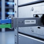
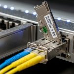
OPC UA is sensitive to latency and session stability, so the transceiver must match the fiber plant design and the switch or media converter behavior. In most OT networks, you will use 10G SFP+ or 1G SFP depending on controller aggregation and uplink capacity. Engineers also weigh DOM support, operating temperature, and whether the optics are compatible with your switch vendor’s optics policy.
1G SFP LX (1310 nm, single-mode) for long runs
Best fit: When you have single-mode fiber (SMF) runs from a control cabinet to a distant aggregation switch, often up to 10 km for typical LX optics. Many industrial Ethernet designs use 1310 nm with LC connectors to reduce cost versus 1550 nm long-haul parts. You will frequently see this choice in legacy plants upgrading from copper.
- Pros: Works well for longer SMF distances; widely supported.
- Cons: Requires correct wavelength pairing; SMF cleaning discipline is mandatory.
1G SFP SX (850 nm, multimode) for cabinet-to-floor links
Best fit: Short to medium runs on OM3 or OM4 multimode fiber, often inside a building. SX optics at 850 nm pair well with OM3/OM4 and LC connectors, making them common in retrofit trays where SMF is not available. For OPC UA, the stability is usually excellent when fiber plant polarity and patching are correct.
- Pros: Lowest cost per port; easy installation on MMF.
- Cons: Distance depends heavily on OM grade; overcrowded bundles increase attenuation.
1G SFP BiDi (1310/1550 nm) to reuse existing fiber pairs
Best fit: When you must reuse old cabling with limited fiber count, BiDi optics allow two wavelengths over the same strand pair. Typical implementations use 1310 nm transmit on one end and 1550 nm transmit on the other. This is useful in brownfield plants where pulling new fiber is expensive and shutdown windows are constrained.
- Pros: Higher fiber utilization; reduces trenching and outages.
- Cons: Must use matched partner optics; mixing variants can cause dead links.
10G SFP+ SR (850 nm, multimode) for high-density aggregation
Best fit: When you aggregate multiple OPC UA gateway devices (or historian/edge compute) into a top-of-rack or end-of-line switch at higher throughput. SR optics at 850 nm target multimode fiber and are common with OM3/OM4. If you are building a leaf-spine edge fabric, 10G SR is often the fastest path to higher uplink bandwidth.
- Pros: Good for dense switch ports; strong ecosystem support.
- Cons: Distance is limited by MMF quality; verify OM3 vs OM4 budget.
10G SFP+ LR (1310 nm, single-mode) for plant-wide uplinks
Best fit: SMF uplinks between buildings, or between control rooms and process cells. LR optics at 1310 nm are widely used for up to 10 km class links, balancing cost and reach. For OPC UA, you are typically protecting session continuity across redundant paths, so stable optical power and proper link budgets matter.
- Pros: Stable reach; predictable behavior with SMF.
- Cons: Requires accurate link budget and connector cleanliness.
10G SFP+ ER (1550 nm, single-mode) for extended reach
Best fit: When you need longer SMF spans than LR supports, such as remote substations or long intra-site runs. ER optics at 1550 nm are designed for extended reach and better attenuation characteristics over distance. This option can reduce the number of intermediate media converters, simplifying maintenance and lowering failure points.
- Pros: Longer reach over SMF; fewer repeaters.
- Cons: More expensive; must confirm transceiver and fiber design compatibility.
SFP with robust DOM support for OT monitoring and faster fault isolation
Best fit: Any OPC UA network where you want faster MTTR by reading transceiver health metrics. Digital Optical Monitoring (DOM) exposes laser bias current, received power, and temperature. In OT operations, this helps correlate OPC UA session drops with optical degradation before complete failure.
- Pros: Better observability; supports proactive replacement.
- Cons: Some switches enforce optics compatibility policies; test in a staging rack.

Key specs that decide whether your SFP link stays up for OPC UA
For OPC UA, your main objective is link stability and predictable latency. Choose optics based on wavelength, reach, and fiber type (MMF vs SMF), then validate power budgets and connector loss. Also check temperature range because OT cabinets often exceed office conditions, especially near drives and transformers.
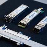
| Spec | Example SFP Type | Typical Wavelength | Fiber | Reach Class | Connector | DOM | Operational Temp (typ.) |
|---|---|---|---|---|---|---|---|
| Data rate | 1G SFP / 10G SFP+ | Depends on type | MMF or SMF | Varies | LC | Often available | -5 to +70 C (varies by model) |
| Multimode short reach | SFP SX | 850 nm | OM3/OM4 | Up to ~550 m (varies) | LC | Common | Industrial variants available |
| Single-mode reach | SFP LX / SFP+ LR | 1310 nm | SMF | Up to ~10 km (varies) | LC | Common | Industrial variants available |
| Extended single-mode reach | SFP+ ER | 1550 nm | SMF | Up to ~40 km (varies) | LC | Common | Industrial variants available |
Selection takeaway: DOM is not just for dashboards; it is a practical tool for isolating whether OPC UA issues correlate with optical power drift. For standards context, the Ethernet physical layer behavior aligns with IEEE 802.3 transceiver specifications and vendor datasheets for SFP/SFP+ optics. For OPC UA transport behavior, remember that reliable sessions depend on stable underlying network reachability and timely link recovery. anchor-text: IEEE 802.3 physical layer standards anchor-text: OPC Foundation resources

Real-world scenario: OPC UA over fiber in a leaf-spine edge zone
In a 3-tier data center style deployment adapted for OT, a factory uses 48-port 10G ToR switches in each process cell. Each cell aggregates traffic from 12 OPC UA gateways and 6 PLC subnets into two redundant uplinks, totaling 24 active 10G SFP+ ports per cell pair. The building uses OM4 multimode fiber for intra-floor runs of 300 m, and SMF for cross-room links of 2 to 6 km. Engineers chose SR for the OM4 segments and LR for the SMF segments, then enabled DOM polling to alert when received power drops below vendor thresholds.
During a seasonal temperature spike, a subset of links flapped. DOM telemetry showed rising laser temperature and falling receive power on one vendor batch, and connector re-cleaning restored stable OPC UA sessions within hours. This is the practical difference between guessing at optics and instrumenting optical health from day one.
Selection criteria and decision checklist for factory automation fiber SFPs
- Distance and fiber type: Confirm MMF grade (OM3 vs OM4) or SMF design. Validate with vendor reach and attenuation budgets.
- Wavelength pairing: Ensure both ends match (e.g., 1310 nm with LR/LX, 850 nm with SX). For BiDi, use matched partner labels.
- Switch compatibility policy: Some enterprise switches enforce optics allowlists; test third-party modules before rollout. Check vendor compatibility matrices.
- DOM support and telemetry exposure: Confirm that your switch actually reads DOM fields you need for alarms and thresholds.
- Operating temperature and thermal design: Prefer industrial-grade optics rated for cabinet conditions. Measure typical cabinet air near the SFP cage.
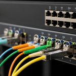
- Connector quality and cleaning process: LC connectors require inspection and cleaning; plan for dust caps and inspection tools.
- Vendor lock-in risk and spares strategy: Decide whether you standardize on OEM or accept third-party with documented compatibility. Stock spares by lot or model for faster swaps.
Pro Tip: In OT environments, the most common “mystery” OPC UA outage is not protocol failure; it is optical degradation masked as network flaps. Set an alert on DOM received power trend slope, not just absolute thresholds, so you catch connector contamination or aging before total link loss.
Common mistakes and troubleshooting patterns (and how to fix them fast)
Wrong wavelength or mismatch between ends
Root cause: Installing SX (850 nm) on one side and LR (1310 nm) on the other, or mixing BiDi variants. The link may never come up or may come up intermittently.
Fix: Verify part numbers and wavelength labels at both ends, then re-seat optics and re-check polarity and fiber patching. Use a fiber inspection scope to confirm connector cleanliness before swapping.
Overestimating multimode reach on OM3 vs OM4
Root cause: Assuming “multimode is multimode” and selecting SR optics without calculating loss for the specific OM grade, patch cord lengths, and bend radius. Attenuation increases with aging and poor handling.
Fix: Measure end-to-end loss with an OTDR or optical power meter, then compare to the vendor’s link budget. If margin is tight, move to OM4-appropriate optics or switch to 1310 nm SMF optics.
Ignoring optics compatibility and DOM behavior
Root cause: Some switches treat non-OEM optics as “unsupported,” dropping the port into err-disabled