Server Rack Fiber: ToR Cabling and Transceiver Choices That Hold Up
In a top-of-rack switching build, the smallest decision in server rack fiber selection can ripple into outages, flaky optics, and costly field swaps. This guide helps data center operators, cabling teams, and field engineers choose transceivers and patching practices for reliable ToR-to-aggregation links. You will get concrete reach targets, compatibility checks, and troubleshooting moves you can use on site. It is written for environments where uptime matters and every panel has a schedule.
ToR cabling reality: what fails first in server rack fiber
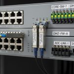
Most ToR link issues start at the interfaces: dirty connectors, mismatched fiber type, incorrect polarity, or optics that the switch does not actually support. In practice, a ToR design often runs short-reach optics like 10G-SR or 25G-SR between servers, ToR switches, and nearby aggregation. Engineers typically plan for patch cords, a predictable bend radius, and consistent labeling so that “which port is which” stays true during change windows.
For short-reach Ethernet, the IEEE physical layer expectations are defined in the relevant 10G and 25G standards, including optics behavior and electrical/optical signaling assumptions. Always verify the switch vendor’s optics compatibility list and firmware notes before you commit spares. For standards-level grounding, review Source: IEEE 802.3 and vendor datasheets for module compliance details.
Operational constraints you can measure during installation
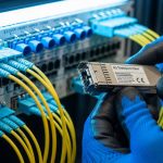
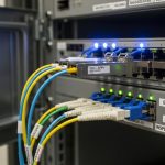
Before you close a rack door, measure what matters: connector cleanliness, patch cord length, and bend radius. Use a handheld fiber scope for inspection and aim for a “no visible debris” result; if you see scratches or haze, replace the patch cord. Confirm polarity using either the LC duplex convention (Tx to Rx) or the MPO mapping required by the specific transceiver. When routing inside a rack, maintain a bend radius consistent with the cable jacket spec, commonly at least 10x the cable diameter for many indoor patch cords, and never exceed the vendor’s minimum.

Transceiver selection by reach, wavelength, and connector type
Choosing optics is not just a matter of “SR vs LR.” It is reach budgeting, fiber type (OM3 vs OM4 vs OS2), connector style (LC vs MPO), and power class behavior that match the switch’s port expectations. For ToR, short-reach is dominant, but you may still mix in longer reach for spillover to end-of-row aggregation or cross-row cabling. Plan to standardize on one or two module families to keep spares, labels, and maintenance fast.
Common ToR optics you will actually deploy
- 10G SR (typically 850 nm) for short distances over multimode fiber.
- 25G SR (typically 850 nm) for higher throughput over OM4/OM5.
- 40G SR4 using MPO-8 with parallel optics on multimode.
- 100G SR4 using MPO-12 with parallel optics on multimode.
- Longer reach variants (LR, ER, or CWDM) when you cannot stay within multimode reach budgets.
Spec table: what to compare before you buy
Use this table as a baseline comparison when you are deciding what fits your server rack fiber plan. Always confirm exact part numbers against your switch model and the vendor’s optics compatibility list.
| Optics class | Typical wavelength | Fiber type | Connector | Reach (typical) | Data rate | Operating temp (common) | Power/DOM notes |
|---|---|---|---|---|---|---|---|
| 10GBASE-SR SFP+ | 850 nm | OM3/OM4 | LC duplex | ~300 m (varies by OM) | 10.3125 Gbps | 0 to 70 C or -10 to 70 C | Digital optical monitoring often supported; verify DOM support |
| 25GBASE-SR SFP28 | 850 nm | OM4/OM5 | LC duplex | ~100 m to 150 m (varies) | 25.781 Gbps | 0 to 70 C or -10 to 70 C | DOM via I2C; confirm switch reads it |
| 100GBASE-SR4 QSFP28 | 850 nm | OM4/OM5 | MPO-12 | ~100 m (varies) | 103.125 Gbps | 0 to 70 C | DOM supported in many modules; polarity mapping critical |
| 100GBASE-LR4 QSFP28 | 1310 nm | OS2 | LC duplex | ~10 km | 103.125 Gbps | -5 to 70 C or 0 to 70 C | DOM typically present; wavelength stability matters |
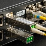
If you need vendor-grade examples for inventory planning, check optics families like Cisco-branded SR modules and common third-party equivalents. For instance, Finisar/FiberMall style 25G/100G parts appear frequently in the field; verify exact compatibility before ordering. As concrete examples, you may see parts such as Source: Finisar and Cisco SFP/SFP28 listings in vendor catalogs. Also check FS.com and similar suppliers for OM5-rated SR modules (example listings include SFP-10GSR-85 and 10G/25G SR variants), but treat them as candidates, not guarantees, until your switch ports confirm behavior.

Compatibility checks that prevent rack-day surprises
Switch vendors often enforce optics behavior through firmware checks: module type identification (EEPROM), digital optical monitoring registers, and sometimes vendor-specific thresholds. Even when an optic is “standards compliant,” a mismatch in DOM support, transceiver type, or temperature class can lead to port flaps. Treat compatibility as a step in the build, not an afterthought.
Checklist: selection criteria for server rack fiber
- Distance and reach budget: sum patch cords, slack loops, and panel-to-panel runs; keep margin for aging and connector variability.
- Fiber type and grade: OM3 vs OM4 vs OM5 for 850 nm SR; OS2 for 1310/1550 nm long reach.
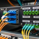
- Connector geometry: LC duplex for most SR; MPO for 40G/100G parallel optics; confirm dust caps and cleanliness workflow.
- Switch compatibility list: verify the exact module family is supported for your switch model and software version.
- DOM support: confirm the switch reads DOM (Tx/Rx power, temperature) and that alerts map correctly to your monitoring stack.
- Operating temperature class: match the module spec to your rack thermal profile; avoid “works on bench” modules in hot rows.
- Vendor lock-in risk: weigh OEM optics availability versus third-party BOM savings; plan for spares and RMA handling.
- Power and thermal budget: confirm module power draw does not exceed the port cage thermal design under sustained load.
Pro Tip: In parallel optics (MPO-based 40G/100G), most “mysterious” link failures are polarity mapping mistakes, not fiber damage. Before you test, verify the MPO key orientation and lane ordering against the patch panel labeling; then confirm with a known-good jumper set and a fiber scope on both ends.
Deployment scenario: a realistic ToR build with measurable targets
Imagine a 3-tier data center with a leaf-spine topology: 48-port ToR switches in each server row, each ToR serving 24 servers at 25G. The cabling team uses OM4 for rack-local links, with patch cords averaging 3 m from server NIC to top-of-rack patch panel. For aggregation, the design uses either short MPO-based uplinks within the same row or longer OS2 runs to a nearby aggregation block.
In this scenario, engineers deploy 25GBASE-SR SFP28 optics for server-to-ToR connections and 100GBASE-SR4 QSFP28 for ToR-to-spine uplinks. Each link is tested end-to-end using a certified OTDR or tiered certification workflow; insertion loss and reflectance traces are stored for audits. During commissioning, they validate DOM readings in the switch telemetry: Tx/Rx power values must fall within the vendor’s recommended operating window, and any warning thresholds trigger a patch cord swap before traffic is cut over. The result is fewer “works for five minutes” incidents and faster root cause isolation when a single connector is contaminated.

Common mistakes and troubleshooting moves in server rack fiber
Even careful teams can stumble. Below are frequent failure modes, with root causes you can identify quickly and solutions that restore service without guesswork.
Port comes up intermittently, then goes dark
Root cause: Dirty connectors or micro-scratches on LC/MPO ferrules cause intermittent optical coupling. In high-traffic deployments, small contamination can be enough to push the receiver below sensitivity.
Solution: Inspect both ends with a fiber scope, clean with approved methods (no improvised wipes), and replace any patch cord with visible damage. Re-test after every cleaning, and keep a “cleaning verification” step in the runbook.
Link never establishes, but light levels look plausible
Root cause: Polarity mismatch (Tx/Rx swapped) or incorrect MPO lane mapping. This is especially common when patch panels are labeled inconsistently during cable moves.
Solution: Confirm polarity with a known-good jumper set; for MPO, verify key orientation and lane order. Update labels so the mapping is unambiguous, and document the correct Tx/Rx mapping in the rack as-built.
Switch reports “unsupported transceiver” or port flaps on upgrade
Root cause: DOM register differences, EEPROM identification mismatches, or switch firmware changes that tighten validation. Sometimes the optic is compatible on one software version but not another.
Solution: Check the switch release notes for optics compatibility changes, then re-qualify the exact module part number. If necessary, move to an optics family explicitly listed for your software and hardware revision.
Excess errors under load despite passing basic checks
Root cause: Link budget exceeded due to long patch cords, additional patch panel mated interfaces, or degraded fiber from improper handling. In multimode, bandwidth-limiting effects and modal dispersion can show up as BER rises.
Solution: Recalculate loss budget, measure end-to-end attenuation with certification tools, and shorten the path or replace with higher-grade fiber (for example, OM4/OM5 where design allows). If you must keep length, validate that the module is rated for the fiber grade used.
Cost and ROI: how to budget server rack fiber without regret
Pricing varies by data rate, vendor, and supply conditions, but realistic ranges help planning. OEM optics often cost more per module, yet they can reduce integration risk and speed RMA cycles. Third-party modules can cut upfront BOM, but you must account for qualification time, potential firmware incompatibilities, and higher failure variance if procurement is not controlled.
As a rough planning band: short-reach optics can range from tens to low hundreds of dollars per module depending on speed class, while QSFP28 100G SR modules are usually higher. Over a year, TCO is dominated by labor for troubleshooting, downtime risk, and replacement logistics, not just purchase price. For ROI, standardize part numbers, keep a labeled spares kit per rack group, and track failure rates by lot code when you can.
FAQ
Q: What fiber type should I use for server rack fiber with 25G SR optics?
A: For typical 850 nm SR deployments at 25G, OM4 or OM5 is the common target. Confirm your module datasheet reach with the exact fiber grade and patch cord lengths, then validate with certification results.
Q: Do I need DOM support for ToR monitoring?
A: If your operations team relies on telemetry, yes. Many switches can read digital optical monitoring for Tx/Rx power and temperature; verify that your transceiver and switch firmware expose the fields your monitoring stack expects.
Q: How do I avoid polarity mistakes with MPO uplinks?
A: Use consistent patch panel labeling and confirm key orientation and lane mapping before you close the rack. Keep a known-good MPO jumper set for validation and record the correct mapping in the rack as-built.
Q: Are third-party optics safe for production?
A: They can be, but only after you qualify them against your switch model and software version. Test with representative patch cords, check DOM behavior, and ensure the vendor lists the correct transceiver type for your port.
Q: What should I do first during a fiber link troubleshooting event?
A: Inspect and clean connectors first, then confirm polarity and mapping, then check switch optics identification and DOM readings. Finally, re-measure loss and confirm you are within the module’s reach and power budget.
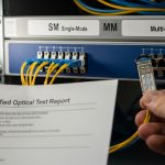
Q: What is the best way to store certification evidence for audits?
A: Save OTDR or certification reports per link ID, including date, operator, tool settings, and trace summaries. Tie each report to your rack and patch panel port labels so you can correlate telemetry alerts to physical-layer evidence quickly.
Choosing server rack fiber is an exercise in disciplined details: reach budget, connector hygiene, polarity mapping, and optics compatibility. If you want the next step, review fiber patch panel labeling and build a labeling and jumper policy that your future self will thank you for.
Author bio: I photograph and document real rack builds, focusing on composition of cables and the small physical cues that predict failure. I also work as a field-minded writer who translates vendor optics specs into on-site checklists for engineers and cabling teams.