When a leaf-spine network starts flapping links or refuses to negotiate line rate, the root cause is often not the optics, but the QSFP module guide decisions made during ordering and installation. This article helps network engineers and field technicians choose the right QSFP transceiver modules for 40G and 100G deployments, validate compatibility, and troubleshoot fast. You will get practical selection checklists, a specs comparison table, and failure-mode fixes grounded in vendor behavior and IEEE fundamentals.
What a QSFP module guide must cover in real deployments
A QSFP transceiver is the pluggable optical/electrical interface that converts switch ASIC signals into fiber-optic (or copper) signals. In practice, engineers must align four systems: the switch port electrical expectations, the optics form factor, the optical fiber plant characteristics, and the operational policy (DOM telemetry, power, and temperature). The IEEE 802.3 family defines Ethernet physical-layer signaling, but vendor implementations vary in how strictly they enforce interoperability. For baseline standards, start with [Source: IEEE 802.3] and then confirm with the specific switch and optics datasheets.
Key QSFP families you will actually see
QSFP is the form factor; the “speed generation” determines modulation and lane mapping. QSFP+ commonly carries 40G using four lanes at 10G each, while QSFP28 carries 100G using four lanes at 25G each. Some platforms also use QSFP-DD for higher density, but your ordering workflow should start by matching the switch port labeling and supported part numbers.
For optical reach and wavelength classes, you will typically choose between SR (short reach, multimode), LR/ER (longer reach, single-mode), and CWDM variants depending on availability and transceiver type. The exact wavelengths and supported fiber types are always in the module datasheet and the switch vendor’s compatibility list.
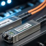
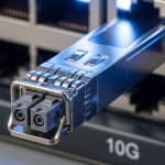
[[IMAGE:Ultra-realistic macro photography of a QSFP28 optical transceiver plugged into a 1U switch port, visible LC duplex fiber connectors in the foreground, shallow depth of field, cool LED rack lighting, high detail metal shielding texture, 50mm lens look, neutral background blur, no logos readable]
QSFP module specifications that decide link success
Specs matter because a “compatible-looking” module can still fail due to fiber type mismatch, lane mapping differences, or transceiver power and temperature constraints. The goal is to translate switch port requirements into optics parameters that the transceiver must satisfy. Engineers often focus on wavelength and reach first, then verify DOM support, optical budget margins, and connector cleanliness requirements.
Minimum spec checklist for 40G and 100G
At procurement time, capture these parameters for every candidate SKU: data rate (40G or 100G), form factor (QSFP+ or QSFP28), wavelength, reach, fiber type (OM3/OM4/OS2), connector (LC duplex is most common for fiber), transmit power and receiver sensitivity (for optical budget), and operating temperature. Then confirm DOM behavior if your monitoring stack expects it.
Side-by-side comparison: common 10G-lane and 25G-lane optics
The table below compares typical QSFP+ SR (40G) and QSFP28 SR (100G) optics seen in data centers. Exact values vary by vendor, so treat this as a planning template and validate against the specific datasheet. For standards context, note that Ethernet PHY characteristics are tied to IEEE 802.3 clauses, but optics particulars are vendor-specific. anchor-text: IEEE 802.3 physical layer reference
| Parameter | QSFP+ SR (40G) | QSFP28 SR (100G) | Typical Example SKUs |
|---|---|---|---|
| Form factor | QSFP+ | QSFP28 | Cisco SFP-10G-SR is for SFP+, not QSFP; use QSFP equivalents per switch |
| Line rate | 40G Ethernet | 100G Ethernet | 40GBASE-SR and 100GBASE-SR per IEEE 802.3 |
| Lane rate and mapping | 4 x 10G lanes | 4 x 25G lanes | Lane mapping must match switch port type |
| Wavelength | Typically ~850 nm (multimode) | Typically ~850 nm (multimode) | Vendor-specific but SR is usually 850 nm class |
| Reach (planning) | ~100m to ~150m on OM3/OM4 class (varies) | ~100m to ~150m on OM4 class (varies) | Examples: Finisar FTLX8571D3BCL (QSFP28 100G SR class), FS.com QSFP28-100G-SR (varies by OM spec) |
| Fiber type | Multimode (OM3/OM4) | Multimode (OM3/OM4), often OM4 preferred | Confirm OM grade in as-built drawings |
| Connector | LC duplex | LC duplex | Some vendors use MPO/MTP for higher density; confirm per module |
| DOM | Often supported; verify I2C/Digital diagnostics | Often supported; verify thresholds and alarms | DOM expectations vary by switch OS |
| Operating temperature | Commercial or industrial grades exist | Commercial or industrial grades exist | Always match your cabinet ambient and airflow profile |
Choosing optics by compatibility, not just reach
Engineers commonly fail by picking “the right reach” while ignoring switch optics policy. Many switch families enforce optics compatibility using vendor IDs, EEPROM fields, or transceiver vendor lock behavior. Even if the module lights up, the port may refuse to come up at target speed if the switch cannot validate the transceiver. Always cross-check the switch vendor’s compatibility matrix and the optics datasheet before you unbox.
Selection criteria / decision checklist
- Distance and fiber type: verify OM3 vs OM4 vs OS2 from the fiber records; do not rely on “looks like multimode.”
- Switch port mapping: confirm whether the port expects QSFP+ vs QSFP28; ensure lane mapping and breakout behavior match your design.
- Wavelength class and reach: SR for multimode, LR/ER for single-mode; validate reach using the vendor’s optical budget model, not a generic rule of thumb.
- Connector and fiber harness: LC duplex vs MPO/MTP; confirm polarity and MPO keying direction if MPO is used.
- DOM support: confirm your monitoring stack can read temperature, bias current, TX power, and Rx power; match thresholds to your alerting system.
- Operating temperature: check module grade and your rack ambient at the switch intake; high fan failure events can push modules beyond spec.
- Budget and TCO: compare OEM vs third-party while factoring failure rates, warranty terms, and swap labor.
- Vendor lock-in risk: if your platform strictly validates EEPROM fields, test with a pilot before rolling out at scale.
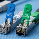
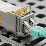
[[IMAGE:Clean vector illustration comparing QSFP+, QSFP28, and QSFP-DD outlines on a workbench, with labeled connectors and lane icons, flat design style, high contrast colors, white background, crisp typography-like shapes without readable brand names]
Real-world deployment scenario: 3-tier leaf-spine with mixed speeds
In a 3-tier data center leaf-spine topology with 48-port 10G and 8-port 100G ToR uplinks, the operators upgraded spine-to-leaf capacity from 40G to 100G. They used QSFP+ SR modules for legacy 40G links over OM3 trunks limited to 82 m, while new QSFP28 SR modules were placed on the 100G uplinks over OM4 runs of 65 m. After a failed rollout, they discovered that two cabinets had transposed MPO polarity in the patch panels, causing intermittent Rx power dips and CRC errors. The fix was not a module swap alone; it required restoring polarity, cleaning LC/MPO endfaces, and verifying optical power thresholds reported via DOM.
Pro Tip: In many switch OS implementations, “link up” can occur before the optics reach stable thermal equilibrium. If you run link tests immediately after hot-plug, you may capture false negatives. Wait for DOM-reported TX bias and temperature to stabilize (often a few minutes) before concluding the module is incompatible.

Installation and validation workflow that field engineers trust
A repeatable workflow prevents costly rework. Start with mechanical inspection (no bent pins, correct cage fit), then validate fiber harness polarity and connector type, and finally confirm link parameters in the switch CLI and telemetry. If you need to troubleshoot quickly, record DOM values and interface counters at the same timestamps.
Step-by-step validation
- Pre-check: verify the switch port accepts the module form factor (QSFP+ vs QSFP28) and that the transceiver is listed in the platform compatibility guidance from the vendor.
- Fiber check: confirm connector style (LC duplex vs MPO/MTP) and clean endfaces using approved lint-free wipes and alcohol-compatible cleaning tools.
- DOM read: confirm temperature, bias current, TX power, and Rx power are within the module’s specified operating range.
- Link bring-up: verify negotiated speed, FEC status if applicable, and interface counters (CRC, symbol errors, discards).
- Stability test: run a sustained traffic test for long enough to observe thermal and link stability, not just a link pulse.
Common mistakes and troubleshooting tips
Most QSFP module failures are avoidable. Below are frequent mistakes with root causes and practical solutions that work in the field.
Port stays down or negotiates at the wrong speed
Root cause: QSFP+ module installed into a QSFP28-capable port that expects different electrical signaling, or the switch enforces EEPROM validation and rejects unsupported transceiver parameters. Solution: verify the exact port type in the switch documentation, then use a module SKU explicitly supported for that platform and speed.
Link up but CRC errors spike under traffic
Root cause: insufficient optical budget margin due to fiber attenuation, dirty connectors, or incorrect polarity on MPO/MTP or duplex LC routing. Solution: inspect and clean endfaces, verify polarity, then compare DOM Rx power readings against the vendor’s expected range. If Rx power is marginal, shorten the patch path or move to a higher-reach optics class.
Intermittent link flaps after thermal cycling
Root cause: module operating outside temperature spec because of restricted airflow, failed fans, or cabinet hotspots. Solution: check rack ambient and airflow paths, replace failing fans, and ensure the optics grade matches your environment. Confirm DOM temperature trends during the flap window.
Monitoring shows “DOM not supported” and alarms flood
Root cause: a third-party optics module provides DOM fields but the switch OS or telemetry agent expects a specific mapping or threshold behavior. Solution: confirm DOM compatibility in the switch OS release notes and validate telemetry parsing rules. If needed, align alert thresholds to the module’s reported ranges.
Cost and ROI: OEM vs third-party QSFP modules
Pricing varies by speed, reach, and volume, but a realistic planning range in many enterprise procurement cycles is: 40G QSFP+ SR often lands in the mid-hundreds to low-thousands USD per module, while 100G QSFP28 SR can be higher depending on OM grade and vendor. Over a 3 to 5 year horizon, TCO is dominated by downtime risk, swap labor, and warranty terms more than the purchase price. OEM optics can reduce compatibility friction, but third-party modules can be cost-effective if they are validated against your switch models and DOM expectations.
Field ROI improves when you run a pilot batch: purchase a small set, validate link stability across representative cabinets, and confirm DOM telemetry and alerting behavior. If failure rates in your environment are higher than expected, the “cheap per unit” optics can become expensive when you include the cost of service calls and traffic impact.

FAQ
How do I know whether I need QSFP+ or QSFP28?
Check the switch port labeling and the platform’s optics support list. QSFP+ typically maps to 40G (4 x 10G), while QSFP28 typically maps to 100G (4 x 25G). If you install the wrong generation, the switch may refuse to bring the link up or may negotiate incorrectly.
What fiber type should I choose for QSFP SR modules?
For short-reach SR optics, confirm whether your plant is OM3 or OM4. Many 100G SR designs prefer OM4 for margin, especially if patch cords add attenuation. Use as-built records and validate with DOM Rx power after installation.
Do I need DOM telemetry for a stable network?
DOM is not required for the physical link to work, but it is valuable for operations. With DOM, you can catch aging optics, rising temperature, and shrinking optical power before failures occur. If your monitoring stack expects specific DOM fields, test compatibility during rollout.
Can third-party QSFP modules work in enterprise switches?
Often yes, but compatibility is not guaranteed across all switch OS versions. Vendors may validate EEPROM fields and enforce strict part-number support. Run a pilot on your exact switch model and software release before scaling.
Why do links flap only at certain times of day?
That pattern often correlates with thermal changes from airflow, HVAC cycles, or fan load. Verify rack intake temperature and monitor DOM temperature during the window of flaps. If temperature is outside spec, fix airflow first before replacing optics.
What is the fastest troubleshooting sequence when a new QSFP module fails?
Start with connector cleanliness and polarity checks, then read DOM for TX and Rx power and temperature. Next, verify negotiated line rate and interface error counters over a short traffic run. If DOM readings are normal but errors persist, measure attenuation and confirm the fiber class and patch path length.
If you want a smooth rollout, treat this QSFP module guide as a workflow: match port generation, validate fiber plant and DOM behavior, then prove stability in a pilot. Next, expand your design choices with fiber transceiver compatibility matrix.
Author bio: I have deployed and validated QSFP and QSFP28 optics in production data centers, including incident response using DOM telemetry and interface error counters. I write with field constraints in mind: airflow, patch-panel polarity, and switch OS compatibility behavior under real traffic loads.