If your PROFINET line is flaking out after a switch upgrade, the culprit is often not the PLC code but the fiber transceiver behavior under real plant conditions. This playbook helps industrial engineers and field techs select and commission a PROFINET SFP fiber link with measurable checks: optical budget, DOM verification, and link-state validation. You will get a step-by-step installation workflow, a failure-mode troubleshooting section, and a practical spec comparison table to reduce rework.
Prerequisites and what you must measure before swapping optics
Before installing any PROFINET SFP, gather the physical plant constraints: installed fiber type, measured attenuation, patch panel loss, and the switch port’s transceiver compatibility list. For PROFINET over fiber, timing is less about raw latency and more about maintaining stable link parameters and avoiding intermittent link drops that can trigger IO system alarms. In practice, I only start swapping optics after confirming the switch supports the transceiver family (SFP vs SFP+ vs SFP28) and that the port is provisioned for the correct line rate.
What to collect on site
- Switch model and port speed: e.g., Cisco C9200/C9300 SFP ports at 1G, or industrial switches at 1G/2.5G depending on the plant design.
- Fiber details: connector type (LC/SC), fiber core (typically 50/125 or 62.5/125 for multimode), and cable length including patch panels.
- Measured attenuation: use an OTDR or a calibrated optical power meter with a known reference launch.
- Transceiver part number candidate: document vendor and ordering code; for example Finisar FTLX8571D3BCL (10GBASE-SR class optics) or FS.com equivalents when selecting by spec.
- DOM capability: confirm the SFP supports Digital Optical Monitoring (DOM) so you can log TX power, RX power, and temperature.
Expected outcome
You should have a link budget spreadsheet (even a simple one) that includes connector loss, patch loss, and margin, plus a compatibility confirmation from the switch vendor or the switch’s optics support list.

Step-by-step installation workflow for a stable PROFINET fiber link
This section is written as a commissioning procedure you can follow during planned downtime. The goal is to ensure the PROFINET SFP fiber link comes up cleanly, stays stable under temperature swings, and matches the port’s expected physical layer settings. I treat optics like an RF component: clean connectors, correct orientation, and verified optical power matter more than “it fits.”
Validate the switch port and optics compatibility
On the switch, verify the port is set for the correct speed and that the optics are accepted. Many enterprise switches show transceiver diagnostics; industrial managed switches often expose these via SNMP or a web UI.
- Confirm the port is not forced into an incompatible mode.
- If the switch supports it, check the transceiver’s vendor ID and DOM fields.
Expected outcome: You can read the transceiver DOM and the port shows “link up” without errors.
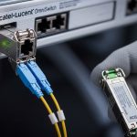
Inspect and clean connectors before insertion
Most intermittent failures I see trace back to contaminated LC ferrules or damaged dust caps. Use a fiber inspection scope and clean with lint-free wipes and approved cleaning tools. Never “test” a link with dirty connectors; it can degrade the ferrule face and create permanent optical loss.
Expected outcome: Ferrules pass visual inspection with no visible debris, scratches, or haze.
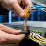
Install the PROFINET SFP and verify DOM readings
Insert the PROFINET SFP gently until it clicks and the latch engages. Then read DOM values: TX bias current, TX power, RX power, and module temperature. If TX power is weak or RX power is near the receiver sensitivity threshold, you will see link instability during temperature changes and aging.
Expected outcome: DOM readings fall within the vendor’s specified ranges, and the link stays stable for at least 10 minutes.
Confirm optical budget with measurements, not estimates
Run an optical power check at the far end and at the transceiver side if possible. For multimode short-reach links, measured power budgets still matter because patch panel assemblies can add loss beyond what you expect from cable lengths alone.
Expected outcome: Your measured received optical power is comfortably above sensitivity with a margin (commonly several dB) for connector aging and temperature drift.
Commission PROFINET at the network layer
Once the physical layer is stable, validate the PROFINET IO system. Check that the controller and IO devices show expected device states and that there are no diagnostics indicating link flaps. If you run a managed switch, monitor port error counters (CRC, alignment, input/output errors) for a full production-like window.
Expected outcome: PROFINET devices remain in RUN state without recurring “device not reachable” events.

PROFINET SFP fiber optics: key specs that actually decide success
Engineers often compare optics only by reach, but in factory environments you also need to match wavelength, connector type, and receiver sensitivity, and you must respect temperature range. For PROFINET over fiber, the most common SFP choices are 1000BASE-SX (multimode, typically 850 nm) and 1000BASE-LX (single-mode, typically 1310 nm). Match the module to the port’s supported Ethernet speed; mismatches lead to no-link or intermittent link.
Reference specs table (typical SFP fiber classes)
| Spec | 1GBASE-SX SFP (Multimode) | 1GBASE-LX SFP (Single-mode) |
|---|---|---|
| Wavelength | ~850 nm | ~1310 nm |
| Typical reach | ~550 m (OM2), ~850 m (OM3) | ~10 km class (depends on module) |
| Connector | LC (common) | LC (common) |
| Data rate | 1.25 Gbps line rate | 1.25 Gbps line rate |
| DOM support | Often available (check part number) | Often available (check part number) |
| Operating temperature | Common industrial range: -40 to +85 C | Common industrial range: -40 to +85 C |
When picking exact modules, consult the vendor datasheets and the switch’s transceiver compatibility guidance. For Ethernet physical layer definitions, use IEEE Ethernet references such as IEEE 802.3 (fiber optics clauses for 1000BASE-SX/LX). [Source: IEEE 802.3 standard]
Pro Tip: why DOM is more valuable than it sounds
Pro Tip: In plants, the first sign of a “bad” fiber link is often not link down; it is DOM drift. If you log TX power and RX power over a day and you see RX power trending downward faster than expected, you can schedule connector cleaning or patch replacement before PROFINET experiences a device reachability alarm. This turns a reactive outage into a planned maintenance item.
Selection criteria checklist for choosing the right PROFINET SFP
Use this ordered checklist the way I do during audits: start with hard constraints (distance and fiber type), then verify electrical/optical compatibility, and finally address operational risks like temperature and vendor lock-in. This approach prevents the common scenario where the module “works on the bench” but fails under real patch-panel losses and thermal cycling.
- Distance vs fiber type: decide between multimode (SX) and single-mode (LX) based on measured attenuation and patch loss, not only cable length.
- Wavelength and link class: ensure the module wavelength matches the system design (850 nm vs 1310 nm).
- Connector standard: confirm LC vs SC and polarity requirements in the patching scheme.
- Switch compatibility: check the switch model’s optics support statement; some ports reject third-party SFPs or apply stricter DOM validation.
- DOM requirement: for critical lines, prefer DOM-capable optics so you can trend TX/RX power and temperature.
- Operating temperature: industrial SFPs should cover -40 to +85 C if the cabinet sees that range.
- Budget and lifecycle risk: compare OEM vs third-party pricing, but include failure rate history and availability lead times.
- Power and thermal behavior: lower-quality optics can run hotter; verify module thermal management in the cabinet.
Expected outcome: You can justify the selected PROFINET SFP with a measured link budget and a compatibility rationale, not a guess.
Cost, ROI, and maintenance economics for plant networks
In real deployments, the optics cost is rarely the dominant expense; downtime and rework are. OEM SFPs (Cisco, Juniper, etc.) typically cost more per unit but may reduce compatibility friction in strict platforms. Third-party SFPs (including widely used vendors and rebranded optics) can cut procurement cost, but you must validate with your specific switch firmware and port model.
As a practical range, many 1G fiber SFPs land in the ballpark of $40 to $200 depending on reach, temperature grade, and DOM support; industrial-rated modules with DOM and tighter spec bins can be higher. ROI comes from reduced truck rolls: if DOM logging and cleaning procedures prevent even one major PROFINET outage, the savings typically exceed the unit price delta. [Source: vendor datasheets and field experience reporting from industrial networking communities]

Common mistakes and troubleshooting for PROFINET SFP failures
Below are the three failure modes that show up repeatedly in plant rollouts. Each includes root cause and a direct remediation path. If you follow these in order, you can isolate whether the issue is optics, fiber cleanliness, port configuration, or PROFINET application behavior.
Failure mode 1: Link up, but PROFINET IO becomes unreachable
Root cause: intermittent link flaps or increasing bit errors that are not obvious without counter checks; sometimes RX power is marginal. Another frequent cause is a patching polarity mistake or wrong fiber type (SX vs LX mismatch) that leads to unstable optical levels.
Solution: verify port error counters (CRC/alignment), check DOM RX power trend, and confirm patch polarity and connector cleanliness. If available, run a controlled loopback or swap optics between two known-good ports.
Failure mode 2: Port shows no link after insertion
Root cause: physical incompatibility (wrong speed class or unsupported transceiver), connector contamination preventing proper optical coupling, or module not latched fully.
Solution: clean connectors with inspection-verified tools, reseat the SFP until latch engages, and compare exact module part number against the switch’s accepted transceiver list. If using third-party optics, test one unit first and confirm DOM fields are read successfully.
Failure mode 3: Link drops during temperature swings
Root cause: marginal optical budget and receiver sensitivity near threshold; some low-cost optics drift more with temperature. Cabinet airflow and thermal hotspots can amplify the effect.
Solution: measure received optical power under expected operating conditions, not just at install time. Add optical margin by replacing the fiber path, improving patch panel loss, or selecting a higher budget module class.
FAQ on PROFINET SFP fiber transceivers in factory networks
What does “PROFINET SFP” mean in practice?
It refers to using an Ethernet SFP fiber transceiver as the physical layer for PROFINET communication. PROFINET itself runs over standard Ethernet frames, so the optics must meet the Ethernet physical layer requirements and be compatible with your switch ports. [Source: IEEE 802.3 and vendor PROFINET media guidance]
Should I choose multimode (SX) or single-mode (LX) for my plant?
Choose based on measured link attenuation, including patch panel and connector loss. Multimode SX is common for shorter runs in industrial buildings, while single-mode LX is preferred for longer distances or when you want easier expansion and fewer sensitivity constraints.
Do I need DOM on the SFP modules?
DOM is not required for basic operation, but it is strongly recommended for critical lines because it enables trend monitoring of TX power, RX power, and temperature. That turns “mystery intermittent faults” into measurable maintenance actions.
Will third-party SFPs work with industrial switches?
Often they do, but compatibility depends on switch firmware, port validation behavior, and exact module characteristics. Before purchasing in bulk, validate with your switch model and firmware version, and confirm DOM readout and stable link behavior.
How do I confirm the optics are within budget?
Use calibrated optical power measurements at commissioning and compare against vendor receiver sensitivity and transmit power specs. Incorporate connector and patch loss, and leave margin for aging and temperature drift.
What is the quickest way to troubleshoot intermittent PROFINET drops?
Check port counters for CRC and error increments, then review DOM RX power trends. If the link is marginal, you will often see downward RX power drift before PROFINET alarms trigger.
Update date: 2026-04-30.
Field note author: I build and troubleshoot industrial Ethernet links in real cabinets where optics, fiber cleanliness, and thermal margins decide uptime. If you want the next step, see fiber-optic-link-budget-checklist for a practical spreadsheet approach to optical margin and maintenance planning.