When your studio or venue network has to stay rock-solid through live show peaks, the wrong transceiver can mean dropouts, CRC errors, or unexpected link resets. This article helps audio engineers, network techs, and AV integrators choose pro audio fiber SFP modules that fit real switch ports, match optical budgets, and support low-jitter performance. You will get practical selection criteria, deployment examples, and troubleshooting steps you can use onsite.

How pro audio fiber SFP modules fit professional audio networks
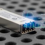
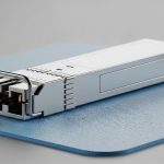
In pro audio and audiophile installations, fiber is often chosen to reduce ground loop risk and electrical noise coupling, especially when long cable runs or mixed power domains exist. An SFP (Small Form-factor Pluggable) brings the optical interface into standard Ethernet switching, letting you transport audio-over-IP reliably while keeping electromagnetic interference low. Many audio-over-IP systems run on standard Ethernet physical layers, so your SFP selection must align with the switch optics and the optical link budget rather than “audio brand” marketing.
From a standards perspective, the electrical and signaling behavior is defined by IEEE 802.3 for Ethernet rates (commonly 1G/10G families). The optical side is constrained by vendor datasheets: wavelength (for example 850 nm for multimode), transmit power, receive sensitivity, and connector type determine whether the link will stay stable under temperature changes and aging. For reference, IEEE 802.3 and vendor SFP datasheets are the primary sources for physical-layer limits and behavior. IEEE 802.3 Standard
Key specifications that actually determine whether the link will stay stable
For audio networks, stability matters more than headline distance because your traffic patterns can stress buffers and trigger link retraining if optics fall out of spec. The most important SFP specs are wavelength, reach class, optical power budget, and transceiver temperature range. In the field, you also need to confirm whether the switch supports DOM (Digital Optical Monitoring) so you can monitor Tx/Rx power and catch degradation early.
Below is a practical comparison of common SFP variants that show up in pro audio and enterprise audio-over-IP deployments. Exact values vary by vendor and part revision, so treat this as a selection starting point and then verify the datasheet for your exact model. FS.com SFP product catalog
| Spec | 10G SR (850 nm MMF) | 10G LR (1310 nm SMF) | 1G SX (850 nm MMF) |
|---|---|---|---|
| Typical data rate | 10.3125 Gb/s | 9.953 Gb/s (10G-class) | 1.25 Gb/s |
| Wavelength | 850 nm | 1310 nm | 850 nm |
| Reach (typical) | Up to 300 m over OM3/OM4 | Up to 10 km over SMF | Up to 550 m over OM2 |
| Connector | LC duplex | LC duplex | LC duplex |
| DOM support | Commonly supported | Commonly supported | Commonly supported |
| Operating temperature | Often 0 to 70 C or extended | Often 0 to 70 C or extended | Often 0 to 70 C or extended |
| Best use | Short/medium runs inside buildings | Long runs between racks or buildings | Legacy 1G audio backbones |
Pro Tip: In many switch platforms, DOM polling is not just “nice to have.” It is your early warning system: if Rx power trends downward by a few tenths of a dB over weeks, you can proactively inspect fiber endfaces and connectors before the link starts flapping during the busiest show hours.
Choosing the right wavelength and fiber type for venues and studios
Wavelength selection is the fastest path to success or failure. 850 nm SFPs pair with multimode fiber (MMF) such as OM3 or OM4 for short-to-medium indoor distances, while 1310 nm SFPs pair with single-mode fiber (SMF) for longer runs. For audiophile and pro audio networks, you often choose fiber because it breaks noisy ground references; however, the physical layer still needs to meet optical budgets under worst-case conditions.
Real deployment scenario: 3-tier leaf-spine with audio VLANs
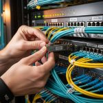
In a 3-tier data center leaf-spine topology with 48-port 10G ToR switches feeding a stage-side audio aggregation rack, the integrator used leaf-to-aggregation links at 10G SR over OM4 multimode cabling for runs up to 120 m. Each aggregation rack hosted a media gateway and multiple audio-over-IP endpoints, with traffic separated into dedicated VLANs and shaped to protect control-plane bursts. During commissioning, they validated optics by checking link error counters (CRC/FCS) and confirming DOM Rx power stayed within the vendor’s specified sensitivity margin. After replacing two connectors that showed microscopic contamination, the link remained stable across 12-hour soak tests and nightly rehearsal peaks.

Selection criteria checklist engineers use on the job
When you pick a pro audio fiber SFP, you are really solving compatibility plus link margin plus operational monitoring. Use this ordered checklist during procurement and staging so you do not discover issues after the crew has already started routing cables.
- Distance and fiber type: Confirm whether you have MMF (OM3/OM4) or SMF and measure the actual run length including patch panels.
- Switch compatibility: Verify the exact switch vendor and model supports that SFP form factor and wavelength. Some platforms enforce vendor/part number allowlists.
- Data rate alignment: Match the port speed profile (for example 10G vs 1G). A mismatched rate can force fallback modes.
- Optical budget margin: Compare Tx power and Rx sensitivity in the datasheet, then include real connector losses (often multiple LC mated pairs and patch panels).
- DOM support: Ensure the transceiver provides DOM and the switch reads it. Plan for monitoring alerts tied to Rx power thresholds.
- Operating temperature range: Studios and venues can see heat buildup in rack bays; confirm whether you need an extended temperature (for example commercial vs industrial).
- Vendor lock-in risk: If the switch requires a specific vendor’s part number, price out the lifecycle cost and consider spares strategy.
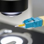
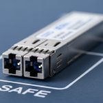
- Connector cleanliness plan: Confirm you have lint-free wipes, approved cleaning tools, and antistatic handling for LC endfaces.
Common mistakes and troubleshooting steps that save hours
Even experienced teams trip over predictable failure modes. Below are concrete pitfalls with root causes and fixes, written for real onsite workflows where you need the link back quickly.
Link comes up, then flaps during load
Root cause: Optical margin is too tight due to underestimated patch losses, aging connectors, or a transceiver with Rx sensitivity near the edge of spec. Solution: Check DOM Rx power and error counters, then re-clean and re-terminate suspect LC pairs. If Rx power is trending down, schedule connector inspection and replace the transceiver with a known-good unit.
Works on the bench, fails in the rack
Root cause: Temperature or airflow differences push the transceiver beyond its operating range, or the switch port is not getting proper thermal management. Solution: Verify rack ambient temperature and airflow, then confirm the SFP’s operating temperature specification. Add airflow paths or adjust fan profiles before replacing hardware again.
“Incompatible optics” messages or no link
Root cause: Switch has a compatibility policy or the SFP is not electrically matched to the platform’s expectations (sometimes also caused by incorrect wavelength or rate). Solution: Confirm the port type and supported transceiver list in the switch documentation. Then try the exact supported part and ensure you are using the correct fiber type (MMF vs SMF, correct wavelength band).
High CRC and intermittent audio artifacts
Root cause: Dirty connectors or micro-scratches on LC endfaces causing signal scattering and increased bit errors. Solution: Clean endfaces with approved methods, inspect with a fiber scope if available, and replace any compromised connectors or pigtails. After cleaning, monitor CRC counters over a full rehearsal cycle.
Cost, ROI, and lifecycle thinking for pro audio fiber SFP
Pricing depends on wavelength, reach, and whether you buy OEM vs third-party. In typical market conditions, 10G SR 850 nm SFP modules often fall into a mid-range price band (commonly tens to low hundreds per module), while 10G LR 1310 nm and extended-temperature variants cost more due to optics and packaging. Your total cost of ownership is driven by spares strategy, downtime risk, and whether the switch enforces vendor lock-in.
From a field ROI perspective, investing in modules with reliable DOM support and buying a small set of known-good spares can reduce mean time to repair during events. Also consider that a small price difference can be offset by connector cleaning supplies, labor hours, and the cost of re-cabling if an incompatible optic forces rewiring. For part examples commonly used in 10G fiber deployments, teams often reference models such as Cisco SFP-10G-SR and Finisar optics like FTLX8571D3BCL, plus third-party alternatives such as FS.com SFP-10GSR-85, but always validate exact compatibility with your switch.
FAQ: pro audio fiber SFP buying questions from real buyers
1) What does “SR” mean for a pro audio fiber SFP?
“SR” typically refers to 850 nm multimode optics designed for shorter distances, commonly up to a few hundred meters depending on fiber type (OM3/OM4) and connector losses. It is a great fit for studio racks and venue in-building runs.
2) Do I need DOM for audio-over-IP links?
DOM is not mandatory for basic link operation, but it is strongly recommended for maintenance. With DOM, you can monitor Tx/Rx power and catch degradation before it causes CRC errors or intermittent audio glitches.
3) Can I mix third-party SFPs with OEM switches?
Often yes, but compatibility varies by switch model and firmware. Some platforms enforce an allowlist, so you should verify the switch’s documented transceiver support before scaling third-party optics across racks.
4) What fiber cleaning method should I use for LC connectors?
Use approved cleaning tools and lint-free materials designed for fiber endfaces, and inspect with a fiber scope when possible. Dirty connectors are one of the most common causes of high CRC counts and “works sometimes” behavior.
5) How do I calculate whether my distance will work?
Start with the module’s Tx power and Rx sensitivity, then subtract estimated attenuation plus connector and splice losses from the vendor’s optical budget guidance. If you do not have a budget worksheet, use the vendor’s reach guidance and add margin for patch panels and worst-case conditions.
6) Why does my link flap only during rehearsals?
Load changes can expose marginal optics, especially when buffers and retransmissions increase error visibility. Check DOM trends and CRC/FCS counters during the rehearsal window, then clean or replace the most suspect connector pair.
If you want clean, reliable transport for audio-over-IP, choose your pro audio fiber SFP by distance, wavelength, optical budget margin, and DOM visibility—not by marketing claims. Next, review best practices for cleaning LC fiber connectors to reduce connector-related errors before you deploy to your main racks.
Author bio: I design and validate fiber-based network interfaces for low-noise, high-availability audio systems in real racks and venues. I focus on optics compatibility, optical budgets, and operational monitoring so teams can ship stable performance under show-time constraints.