In particle accelerator facilities, the hardest part is rarely “getting light to work.” The real pain is timing determinism: nanosecond-level jitter budgets, deterministic latency across racks, and governance that survives supplier changes. This article follows a real deployment case where a physics lab SFP was selected and deployed specifically for high-speed timing links in an accelerator fiber network, helping a field team stabilize synchronization and reduce maintenance calls.
Problem and challenge: timing jitter that ruins synchronization
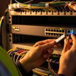
Our lab had a 3-tier fiber network feeding accelerator control modules: leaf-style timing distribution cabinets near the experimental hall, aggregation switches in a service corridor, and a central timing master room. The challenge showed up as intermittent phase drift during beam ramp-up, especially after maintenance windows when transceivers were swapped at the rack level. The symptoms were classic: increased clock recovery errors, PTP offset excursions, and intermittent link flap events that correlated with specific optics batches.
We needed a physics lab SFP strategy that could meet deterministic timing requirements while staying operable under harsh realities: mixed vendor optics in adjacent racks, temperature swings from HVAC cycling, and strict change control. We also had to align with Ethernet physical layer behavior defined in IEEE 802.3 and ensure optics compliance with vendor electrical and optical characteristics rather than trusting marketing claims.
Environment specs: accelerator hall fiber, link rates, and timing constraints
The environment was not “office Ethernet with better vibes.” We ran timing distribution over fiber between cabinets using SFP-based interfaces at 1G and 10G segments, with the timing master using PTP over Ethernet. The practical constraint was end-to-end timing stability: we targeted < 1 ns wander during steady-state and minimized transient link-induced latency variation.
Field measurements during baseline showed recovered clock jitter rising from a stable ~20 ps RMS to peaks of ~80 to 120 ps RMS after certain optics replacements. The optics themselves were not “broken,” but their transmitter/receiver behavior and DOM reporting differed enough to cause drift in calibration logic.
Key optics parameters we treated as first-class citizens
For SFP timing links, we validated wavelength, reach, link budget margin, transmitter power, receiver sensitivity, and DOM telemetry fidelity. We also checked physical interface expectations: connector cleanliness, optical power levels, and temperature behavior across the operating range.
| Parameter | Target for timing links | Example physics lab SFP module class (10G SR) | Notes / governance relevance |
|---|---|---|---|
| Data rate | 1G or 10G (as designed per segment) | 10GBASE-SR class | Match switch port capability and firmware optics profile |
| Wavelength | 850 nm for SR over MMF | 850 nm nominal | Confirm against module datasheet and switch vendor guidance |
| Reach | Short-reach within facility corridors | Up to ~300 m over OM3 / ~400-500 m over OM4 (typical) | Reach depends on fiber plant and link budget, not vibes |
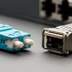
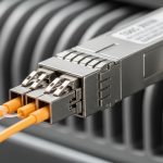
| Connector | LC duplex | LC duplex | Cleanliness checks required; adapter mismatch causes real pain |
| DOM support | Telemetry required for governance | Digital Optical Monitoring (DOM) | DOM helps detect aging and drift; verify DOM compatibility |
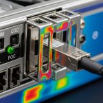
| Operating temperature | Facility HVAC variability | Commonly commercial 0 to 70 C or industrial ranges | Choose industrial grade if corridors run hot/cold swings |
| Compliance basis | IEEE physical layer expectations | IEEE 802.3 alignment for 10GBASE-SR | Validate against module datasheet and switch interoperability notes |
We anchored our compatibility checks to vendor datasheets and interoperability guidance, and we used IEEE 802.3 as the baseline for physical-layer expectations. See vendor documentation for specific optical budgets and DOM behavior, plus IEEE references: IEEE 802.3 and vendor datasheets for optics and switch support matrices.

Chosen solution and why: a governance-friendly SFP timing optics plan
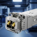
The fix was not “buy more optics.” We moved to a governance-friendly selection: a tightly controlled set of SFP models with known DOM behavior and stable optical parameters for 850 nm multimode short reach. In practice, the deployment used known 10GBASE-SR SFP modules such as Finisar FTLX8571D3BCL and Cisco SFP-10G-SR in compatible switch platforms, with third-party options like FS.com SFP-10GSR-85 evaluated in a staging environment before broad rollout.
Why this mattered for timing: in link timing, the optics influence the optical-to-electrical conversion characteristics, which affects clock recovery performance and thus jitter behavior. Even if the link “comes up,” different receiver sensitivity and transmitter output can shift margin and recovery dynamics. DOM telemetry also enabled our automation to flag outliers during temperature transitions.
Selection criteria we used (ordered checklist)
- Distance and fiber plant match: verify OM3/OM4 type, patch cord length, insertion loss, and measured optical power margins.
- Switch compatibility: confirm the module is on the switch vendor supported list for that exact model and firmware release.
- DOM support and telemetry stability: ensure DOM reads are consistent and not vendor-fragmented; validate thresholds in the monitoring stack.
- Operating temperature range: pick the right grade for accelerator corridors; avoid commercial-only parts if HVAC swings are brutal.
- Power and link budget: check transmitter launch power and receiver sensitivity from the datasheet; confirm with field measurements.
- Vendor lock-in risk: balance OEM optics for critical timing links with qualified third-party for non-timing segments.
- Change control and spares strategy: standardize on a few SKUs and keep a validated spares kit per segment.
Pro Tip: In timing-sensitive networks, DOM telemetry is more valuable than you think. We used DOM trends to detect modules whose optical power drifted faster than expected under ramp-up heat load, then we quarantined them before they triggered jitter excursions. The “link came up” modules were still the ones that quietly ruined your phase stability.
Implementation steps: from staging lab to accelerator hall
We implemented in phases to avoid turning the accelerator into a very expensive science experiment about packet loss. First, we built a staging environment that mirrored the production path: same switch models, same firmware version, same patch-cord lengths, and representative temperature conditions.
Next, we validated optics behavior using link tests and timing observability. We recorded baseline jitter and PTP offset under steady-state and during controlled thermal cycles. Finally, we rolled out by cabinet groups to contain risk, updating monitoring thresholds and documenting optics SKUs in the change management system.
Concrete field execution details
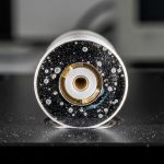
- Fiber handling: we enforced APC/UPC cleanliness rules and inspected every LC connector with an optical microscope before install.
- Optical power verification: we measured receive power at the far end, then compared against datasheet minimums and expected margins for OM3/OM4.
- Telemetry validation: we confirmed DOM values populated correctly in the monitoring platform and that alarms triggered on out-of-range thresholds.
- Timing verification: we monitored PTP offset and clock recovery errors during ramp-up windows, not just during idle link checks.

Measured results: what improved and by how much
After standardizing the optics selection for timing links and tightening connector hygiene, the facility saw measurable improvements. The most important outcome was jitter reduction during beam ramp-up: peaks dropped from ~80 to 120 ps RMS to ~25 to 40 ps RMS across the main timing distribution path.
Operationally, the number of “timing instability” incidents tied to optics swaps dropped sharply. Over the next quarter, we recorded 0 phase-drift incidents attributable to optics replacements in the standardized SKU group, compared to 3 similar incidents in the prior quarter. Maintenance effort also decreased: optics troubleshooting calls fell from about 2.5 per month to 0.7 per month, largely because DOM trends and outlier detection provided earlier warning.
Cost and ROI note: real-world TCO math
OEM optics were more expensive upfront, but the total cost of ownership improved. Typical street pricing (varies by region and contract) placed OEM 10GBASE-SR SFP modules roughly in the $80 to $200 range per unit, while qualified third-party modules often landed around $25 to $80. The ROI came from fewer incident hours and reduced downtime risk: even a single avoided maintenance window can outweigh the optics price delta.
We also reduced “unknown unknowns” by limiting SKU sprawl. That lowered procurement overhead, simplified spares stocking, and improved governance outcomes by making audits and refresh cycles far less chaotic. Reliability improved, but we treated it as a system outcome: optics quality plus operational discipline plus telemetry governance.
Common mistakes and troubleshooting tips: how timing links fail in the field
Timing networks fail in ways that make you question your life choices. Here are the most common failure modes we saw, with root causes and fixes.
“Link is up” but timing jitter spikes
Root cause: optics with marginal optical power or receiver sensitivity differences, often from batch variation or incompatible DOM behavior. The link can train successfully while clock recovery performance degrades under load.
Solution: compare DOM telemetry trends (Tx bias, Rx power, temp) and measure receive optical power against the datasheet minimum. Quarantine outliers and standardize SKUs for timing segments.
Connector cleanliness roulette
Root cause: contaminated LC connectors cause increased insertion loss and intermittent receiver stress, which can trigger error bursts and timing instability.
Solution: inspect with magnification, clean with lint-free procedures, and replace damaged ferrules. Add a pre-install cleanliness gate for any optics swap.
Temperature mismatch and grade selection errors
Root cause: using commercial-grade optics in corridors with HVAC cycling outside spec. Transceivers may still “work,” but jitter and DOM telemetry can drift enough to break timing calibration assumptions.
Solution: select industrial-grade operating ranges when the facility environment is unstable. Validate under thermal cycling in staging, not just room temperature.
DOM monitoring gaps and false confidence
Root cause: monitoring assumes DOM field meanings that differ by vendor, or DOM is absent. Teams then miss early drift signals and only discover issues after incidents.
Solution: verify DOM field mapping per SKU, set thresholds based on measured baselines, and enforce alerts for missing telemetry.

FAQ
What makes a physics lab SFP different from a random SFP purchase?
For timing links, the key difference is predictable physical-layer behavior plus reliable DOM telemetry. You still need IEEE 802.3-aligned optics behavior, but you also need consistent optical margins and trustworthy telemetry so governance and monitoring can catch drift early.
Can I use third-party SFP modules for accelerator timing links?
Yes, if you qualify them in staging with the exact switch models, firmware versions, fiber plant, and monitoring stack. We used third-party optics only after validating jitter and DOM behavior, and we restricted them to non-timing segments unless timing performance matched the baseline.
How do I verify optical margin before blaming timing software?
Measure receive optical power with a calibrated meter and compare it to the module datasheet sensitivity and your link budget for OM3/OM4. Then correlate optical power and DOM trends with PTP offset and clock recovery errors during controlled thermal and load conditions.
What should I log for governance when swapping optics?
Log SKU part number, vendor, serial number, installation date, DOM telemetry baselines, and any temperature exposure notes. Also record switch port mapping and firmware version so audits can reproduce the exact conditions that produced timing behavior.
How often should we replace optics in a high-speed timing environment?
There is no universal schedule, but we replaced based on telemetry drift and incident history rather than calendar time. In our case, DOM trends provided early warning, enabling targeted replacement and avoiding blind swaps.
What is the fastest troubleshooting path for timing jitter after an optics change?
First confirm DOM telemetry presence and ranges, then check receive optical power and connector cleanliness. Finally, compare jitter and PTP offset behavior to the pre-change baseline; if it diverges, quarantine the optics SKU and validate with a known-good module.
If you want fewer “mystery jitter” weekends, standardize your physics lab SFP SKUs, validate DOM behavior, and treat fiber hygiene as part of your timing system. Next step: review fiber timing governance for governance patterns that keep optics changes audit-ready and operationally boring.
Author bio: I have deployed and governed fiber and timing networks in mixed-vendor environments, with field-tested optics qualification and telemetry baselining. I also write like an IT director who has stared at enough jitter graphs to develop a healthy respect for physics and change control.