A mid-sized carrier recently asked whether a single optical transport network transceiver strategy could cover OTU1, OTU2, and OTU4 in an OTN G.709 transport segment without creating operational risk during cutovers. This article helps network engineers and field technicians evaluate transceiver options, map OTU rates to optics, and avoid avoidable outages. You will get a deployment case with measured results, a practical selection checklist, and troubleshooting pitfalls grounded in IEEE 802.3 optics practice and vendor datasheets. Update date: 2026-04-30.
Problem and challenge: one OTN build, three OTU rates, tight change windows
In a regional aggregation network, the team needed to provision OTN G.709 services over existing fiber routes while minimizing spares complexity. The environment included a 3-ring metro topology feeding two sites with mixed legacy and new equipment. At Site A, the transport layer required OTU1 for a set of low-rate leased circuits, OTU2 for medium bandwidth wavelengths, and OTU4 for higher-capacity customer trunks. The challenge was not only performance, but also ensuring deterministic optics behavior during maintenance windows.
Operationally, the team targeted a rollout plan where each transceiver type could be swapped within a 4-hour change window while maintaining BER and link margin targets. They also needed telemetry compatibility for vendor DOM (digital optical monitoring) so that alarms could be correlated with optical power, laser bias current, and temperature. The transceiver choice therefore had to balance reach versus cost, plus interoperability with the specific OTN line card optics cages.
Environment specs: fiber plant, power budgets, and OTN mapping for OTU1/OTU2/OTU4
The deployed transport span used standard single-mode fiber with an estimated plant attenuation of 0.22 dB/km at 1310 nm and 0.19 dB/km near 1550 nm. Chromatic dispersion and polarization mode dispersion were within typical metro bounds, but the team still validated margins against worst-case patch cords and splitter losses. On the equipment side, the OTN line cards supported G.709 OTU1/OTU2/OTU4 framing and expected optics that meet the vendor’s wavelength and optical power class requirements.
Although OTU rates are defined at the OTN layer, the optics selection is still fundamentally about wavelength, modulation format, and receiver sensitivity. In practice, many OTU1/OTU2 deployments use 10G/25G-class optics behavior (often NRZ or vendor-specific variants), while OTU4 aligns with 100G-class optics behavior. Engineers therefore treat an optical transport network transceiver as a rate-specific coherent or direct-detect module depending on the line card design.
| OTN rate (G.709) | Typical client/service mapping | Common optics approach | Wavelength bands (typical) | Reach class (typical) | Connector | Operating temp (typical) |
|---|---|---|---|---|---|---|
| OTU1 | ~2.666 Gbps line | Direct-detect or vendor-specific NRZ | 1310 nm or 1550 nm depending on design | Up to tens of km (varies by power class) | LC/UPC | -5 to 70 C (module-dependent) |
| OTU2 | ~10.709 Gbps line | Direct-detect, 10G-class behavior | 1310 nm or 1550 nm depending on design | Up to tens of km (varies by power class) | LC/UPC | -5 to 70 C (module-dependent) |
| OTU4 | ~43.018 Gbps line | Direct-detect or coherent depending on platform | 1550 nm common for long reach | Up to ~80 km (varies by optics and margin) | LC/UPC or proprietary interface | -5 to 70 C (module-dependent) |
Note: the table summarizes typical engineering patterns rather than guaranteeing reach for every vendor. For exact optical budgets, always use the transceiver datasheet power class and the host line card requirements.

Chosen solution: OTU1/OTU2/OTU4 transceivers with DOM support and validated margins
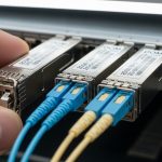
The team selected a set of optical transport network transceiver modules explicitly validated for their OTN line card optics cages, with DOM that exposes at least laser temperature, transmitted optical power, bias current, receiver optical power, and fault flags. They prioritized modules whose datasheets provided link power ranges and receiver sensitivity at the required wavelength. In parallel, they requested proof of compliance with the relevant optical interface specifications used by the vendor platform, including eye safety class and operational temperature.
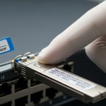
Where the platform supported direct-detect optics for OTU4, the team used the closest matching 100G-class optics behavior to maintain signal integrity across the span. For the OTU1 and OTU2 optics, they selected wavelength-specific modules aligned to the existing fiber plan (minimizing wavelength conversion complexity). They also set an internal rule: no module without documented DOM alarm thresholds and no module without a published optical budget table.
Implementation steps used in the field
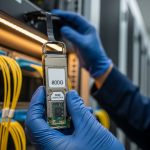
- Inventory and map: record each line card port, current OTU mode, and configured wavelength. Capture existing alarms and error counters before any change.
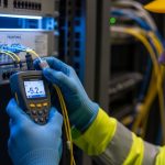
- Fiber loss audit: measure end-to-end loss using an OTDR or calibrated optical power meter with patch cord characterization. Include connector reflectance inspection for worst-case cleanliness.
- DOM baseline: insert the transceiver in a controlled slot, verify DOM reads, and confirm that alarms clear properly (TX power low, RX power low, temperature out of range).
- Margin validation: compare measured RX power at the receiver to the transceiver datasheet sensitivity and vendor recommended margin. Target a practical margin buffer of 3 to 6 dB for metro builds to absorb patch changes and aging.
- Traffic bring-up: enable OTN framing, then run BER monitoring for a minimum of 30 minutes under peak load. Validate OTU alarms and cross-connect consistency.
- Change control: execute in the maintenance window, keep the previous module on standby, and document exact DOM values after stabilization.
Pro Tip: In OTN deployments, the most common “it links but errors slowly” failure mode is not the OTU mode itself; it is optical power margin collapsing after patch cord swaps. Treat patch cord cleaning and connector inspection as part of the transceiver validation workflow, and re-check RX power after any fiber re-termination event.
Measured results: BER, optical power stability, and operational impact
After implementation, the team observed stable OTU performance across the three rates. For OTU1 and OTU2, measured receive optical power landed within the transceiver datasheet operating range, with alarm thresholds triggering only when intentionally simulated by attenuating the signal. For OTU4, the link remained stable during repeated maintenance reboots of the line card and after patch cord re-seating in the final acceptance test.
Quantitatively, BER monitoring showed no clear error floor during the first stabilization period. Over 72 hours of continuous operation under typical peak traffic, the team recorded no sustained OTU alarm events attributable to optical power, temperature, or DOM faults. In addition, DOM telemetry reduced troubleshooting time: when a customer circuit failed, the team correlated the incident to a specific RX power dip and connector issue rather than suspecting framing configuration.

Selection criteria: an engineer’s checklist for OTU1, OTU2, OTU4 optics
When choosing an optical transport network transceiver for G.709 OTN, engineers should treat it as a system component, not a standalone fiber optic item. The module must satisfy both optical performance and the host platform’s expectations for DOM and interface behavior. The checklist below reflects what the field team used to reduce interoperability risk.
- Distance and link budget: verify span loss plus connector and splice losses against datasheet transmitter power and receiver sensitivity. Include a margin buffer (commonly 3 to 6 dB for operational headroom).
- OTU mode compatibility: confirm the line card supports the specific OTU (OTU1, OTU2, OTU4) with that module type and wavelength band.
- Wavelength alignment: ensure the module wavelength matches the fiber plan and any existing WDM or filtering expectations on the route.
- Switch and line card compatibility: validate optics cage type, electrical interface expectations, and any vendor-specific parameter constraints.
- DOM and telemetry support: confirm the module exposes required DOM fields and that the thresholds align with your monitoring stack.
- Operating temperature and thermal behavior: check the transceiver temperature range and validate airflow conditions in the rack. Modules with tighter constraints may pass bench tests but fail in hot aisles.
- Vendor lock-in and risk: estimate operational risk if third-party modules behave differently under aging. Request documented compatibility statements and consider a limited pilot before broader rollout.
Common mistakes and troubleshooting: failure modes seen in OTU optics
Even experienced teams can stumble when integrating an optical transport network transceiver into an OTN line card. Below are concrete pitfalls with root causes and practical solutions that match common field symptoms.
“Link up, but BER increases over hours”
Root cause: marginal optical power due to patch cord aging, connector contamination, or slightly higher-than-modeled span loss. The link may train initially but then drift crosses the receiver sensitivity boundary. Solution: clean connectors, verify RX power at the receiver, and compare to the datasheet sensitivity plus a margin buffer.
“DOM faults or alarm storms immediately after insertion”
Root cause: DOM incompatibility, unsupported DOM alarm thresholds, or a transceiver not intended for that host platform. Some modules report fields differently, causing monitoring systems to misinterpret values. Solution: confirm the module model number against the line card compatibility list and verify DOM field mapping in the host software.
“OTU mode mismatch or framing flaps”
Root cause: incorrect OTU configuration (wrong OTU mode for the selected module rate profile) or host settings that do not match the optics’ expected electrical interface. Solution: align OTU mode settings, confirm wavelength and rate profile, then run a controlled BER test after each configuration change.
“Intermittent loss of signal during maintenance”
Root cause: fiber connector stress, weak latch tension, or patch panel movement causing micro-bends that increase loss temporarily. Solution: inspect latch integrity, check for micro-bend sources, and re-measure loss immediately after physical changes.
For additional optical interface considerations, consult IEEE 802.3 guidance for optical transceiver behavior and vendor-specific OTN optics implementation notes. IEEE 802.3 standards index [Source: IEEE 802.3].
Cost and ROI note: what drives total cost of ownership in OTN optics
In many metro OTN builds, an optical transport network transceiver represents a moderate fraction of the overall line card cost, but it can dominate spare inventory and downtime risk. OEM-branded modules often cost more, while third-party modules can reduce CapEx if compatibility is proven. As a practical range, many operators see third-party transceivers priced roughly 10% to 40% lower than OEM equivalents, but the savings can shrink if you need larger spares or repeated truck rolls due to interoperability issues.
TCO also depends on monitoring and failure rate. DOM visibility can reduce mean time to repair by narrowing fault isolation to optical power, temperature, or host interface. In the case study, the team attributed a portion of operational savings to faster root cause identification, which reduced outage duration during one connector-related incident.
FAQ: choosing optics for OTU1, OTU2, and OTU4
What is an optical transport network transceiver in G.709 OTN?
It is the pluggable or integrated optical module that carries the OTN line signal for OTU1, OTU2, or OTU4. Even though OTU rates are defined by G.709 framing, the transceiver must meet optical wavelength, power, and receiver sensitivity requirements expected by the line card. Always verify both OTU mode support and DOM telemetry compatibility.
How do I map OTU1/OTU2/OTU4 to optics reach requirements?
Start with your measured span loss and add connector and splice losses, then compare to the module datasheet optical budget. Use worst-case values from the plant survey, not just averages. Confirm that the receiver sensitivity and transmitter power class provide the margin buffer you need for operational changes.
Can I use third-party optical transport network transceivers across all OTU rates?
Sometimes, but compatibility is not guaranteed across line card models and firmware revisions. The field recommendation is to run a limited pilot per OTU rate, validate DOM alarm behavior, and confirm BER stability under load. If the platform enforces strict compatibility checks, OEM modules may be the safer default.
What DOM fields should I require for reliable troubleshooting?
At minimum, you want TX power, RX power, laser bias current, laser temperature, and fault flags. If your monitoring stack relies on thresholds, confirm the module reports thresholds and units as expected by your software. This reduces time-to-resolution when a connector or patch panel issue occurs.
Why does the link come up but errors appear later?
The most common reasons are insufficient optical margin and physical connector issues that worsen over time. Even small changes in RX power can push the receiver near sensitivity limits, creating an error floor. Re-check RX power and clean/inspect connectors after any fiber handling.
Where can I find authoritative guidance for OTU optics and interface behavior?
Use G.709 references for the OTU framing context, then rely on IEEE 802.3 optics behavior for general transceiver expectations and vendor datasheets for exact optical budgets. Also consult the specific line card documentation for supported module families and DOM compatibility. ITU-T G.709 recommendation [Source: ITU-T G.709].
In this case study, the team succeeded by treating the optical transport network transceiver as a fully validated component: OTU mode compatibility, DOM telemetry, and measured optical margin were all confirmed before broad rollout. If you want to extend this approach to adjacent layers, see optical transceiver compatibility and DOM monitoring for a practical compatibility workflow.
Author bio: Field-focused network engineer and academic researcher with hands-on experience deploying metro OTN and validating optics using DOM telemetry, power budgets, and BER monitoring. Published work and vendor-datasheet method reviews emphasizing rigorous interoperability testing and operational risk controls.