DWDM transceiver commissioning fails quietly when optical power, channel spacing, or laser drift are off by small margins that a basic power meter misses. This article helps network and optical engineers plan an OSA transceiver test that validates wavelength accuracy, side-mode behavior, and spectral stability before traffic cutover. You will get head-to-head comparisons, a decision checklist, troubleshooting pitfalls, and a practical ROI view for enterprise and carrier-style environments.
OSA transceiver test: what you can verify that power meters miss
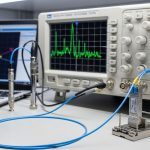
An Optical Spectrum Analyzer (OSA) provides a frequency-domain view of the transmitted signal. In an OSA transceiver test for DWDM transceivers, you typically validate: center wavelength vs ITU grid, optical power per channel, spectral shape (including side lobes), and spectral drift across warm-up and temperature cycles. For coherent and advanced modulation, you also use OSA measurements to catch gross impairments early, even if final performance is validated with BER and end-to-end throughput tests.
Commissioning targets are usually anchored to the DWDM channel plan (commonly ITU-T grids) and the transceiver vendor’s optical specs. IEEE 802.3 defines Ethernet PHY behavior but does not standardize OSA measurement procedures; therefore, engineers rely on vendor datasheets and measurement guidance from reputable optics organizations and vendor application notes. For example, many DWDM deployments still follow legacy assumptions like “wavelength within a fraction of channel spacing” rather than purely relying on receiver lock success.
In field practice, the OSA measurement workflow starts with optics hygiene (connector cleanliness), then baseline measurements with the transceiver in a known state, and only then comparisons against expected wavelength and spectral mask. If your goal is commissioning speed, you also want a repeatable test profile: fixed OSA span, resolution bandwidth, sweep time, and a consistent fiber path with known loss.
Head-to-head: OSA vs alternative commissioning methods
Teams often ask whether an OSA is “required” for commissioning. The realistic answer is that an OSA is the fastest way to confirm spectral alignment and detect non-compliance patterns that can later cause receiver sensitivity issues, mux/demux crosstalk, or unexpected channel contention. However, there are alternatives for specific validation phases, especially when budget and throughput matter.
OSA transceiver test versus power-only checks
A calibrated power meter validates absolute or relative optical power but cannot confirm wavelength, channel occupancy, or spectral leakage. You can pass power thresholds and still fail wavelength alignment, which later shows up as poor demux filtering or receiver lock instability. For DWDM, where channel spacing can be tight, wavelength error is often the hidden cause of intermittent faults.
OSA versus fixed-wavelength channel monitors
Some systems use fixed filters or channel monitoring receivers. These can be faster and cheaper per port, but they are less flexible when you commission mixed optics, non-standard grids, or vendor-specific tuning behavior. If you frequently re-use test setups across different projects, an OSA gives you a single instrument that can measure many channel plans.
OSA versus coherent test equipment (when applicable)
For coherent optics, full performance validation requires modulation-aware measurements (often using dedicated test sets). Still, an OSA transceiver test is valuable for “first-pass triage” to catch laser wavelength drift, abnormal sidebands, or gross spectral distortion before you spend time on deeper DSP-level testing.
| Option | What it measures best | Typical commissioning speed | Key limitation | Best-fit scenario |
|---|---|---|---|---|
| OSA transceiver test | Wavelength, spectral shape, side lobes, drift | Medium to fast (depends on sweep settings) | Higher capex; requires careful calibration and fiber path control | DWDM commissioning, mixed vendors, ITU grid alignment |
| Power-only meter | Optical power level | Fast | No wavelength or spectral mask confirmation | Quick health checks after OSA baseline |
| Fixed filter / channel monitor | Channel presence vs fixed bins | Fast | Limited flexibility across channel plans | High-volume production testing with stable specs |
| Coherent test set | BER, EVM-like metrics, modulation quality | Slower per port | Expensive; setup complexity | Final acceptance for coherent links |
Bottom line: if you are commissioning DWDM transceivers and need spectral assurance, an OSA transceiver test is the most informative single measurement you can run early in the process.

OSA setup choices that affect commissioning outcomes
Even a high-quality analyzer can produce misleading results if span, resolution bandwidth, and reference calibration are inconsistent. For OSA transceiver test planning, you should align your measurement settings to the expected laser linewidth and channel spacing. In practice, engineers set a measurement span that covers at least the intended channel and neighboring leakage region, then choose resolution bandwidth small enough to separate the main peak from side structures.
Key setup elements include: using a stable laser reference or known calibration source if your OSA supports it, ensuring you account for connector and patch cord losses, and keeping the transceiver warm-up consistent. If you are validating DWDM channels, you also want to confirm the OSA wavelength accuracy by checking a known reference line or using the analyzer’s internal calibration routine before the day’s first measurement.
Measurement profile that field engineers reuse
A repeatable commissioning profile might include: fixed OSA wavelength center, fixed span, consistent sweep time, and a standard rule for “measurement after warm-up.” In a typical lab workflow, engineers record three snapshots: immediately after enabling the laser, after warm-up stabilization (often 10 to 30 minutes depending on module and operating class), and after a controlled temperature change if you are validating environmental behavior.
For connectorized optics, you also need to standardize the launch conditions. A common failure mode is inconsistent fiber launch due to dirty connectors; that can look like spectral broadening or apparent power dips. Therefore, cleaning and inspection are not optional steps.
Pro Tip: In DWDM commissioning, many “mystery wavelength errors” are actually artifacts of an uncalibrated wavelength axis in the OSA plus an inconsistent fiber path. Before chasing transceiver tuning issues, verify the OSA wavelength calibration against a known reference line and keep the same patch cord and adapter stack for every port.

Cost and ROI: when OSA transceiver test pays off
Budget decisions depend on how many ports you commission, how often you re-run tests, and how expensive downtime and rework are. OSA instruments range from lower-cost benchtop models to high-accuracy systems; installed costs can include calibration services, fiber test accessories, and maintenance contracts. In enterprise deployments, the ROI often comes from reducing “truck rolls” and avoiding late-stage link failures that require rework in the field.
Typical cost ranges vary widely by performance class. As a planning order-of-magnitude: a mid-range OSA suitable for DWDM wavelength measurements might cost tens of thousands of dollars, while higher accuracy systems can reach substantially more. Third-party transceiver vendors can reduce module capex, but you still need measurement confidence; the OSA is your quality gate. The highest ROI comes when you standardize a test profile and build a repeatable acceptance record that can be audited during outages.
TCO also includes measurement time. Faster sweep settings can reduce throughput time but may reduce spectral fidelity. If you commission hundreds of ports, you may choose a two-tier process: a quick OSA transceiver test for spectral alignment, followed by deeper analysis only for out-of-spec channels. This strategy reduces total analyzer runtime while keeping risk under control.
Decision checklist: choosing the right OSA transceiver test approach
Use this ordered list during planning. It reflects how optical engineers prioritize risk reduction and operational constraints.
- Distance and channel plan: confirm whether you are validating ITU grid alignment (spacing and wavelength range).
- Budget versus accuracy: match OSA wavelength accuracy and resolution bandwidth to the tolerance your transceiver requires.
- Switch and mux/demux compatibility: ensure your DWDM mux/demux filtering expectations align with your wavelength verification method.
- DOM and transceiver diagnostics: if you rely on Digital Optical Monitoring, ensure DOM readings correlate with OSA measurements and vendor expectations (temperature and bias can explain drift).
- Operating temperature range: verify the transceiver and OSA environment stability; record measurements after warm-up and, if required, after thermal cycling.
- Calibration and reference strategy: define how you verify wavelength axis accuracy before commissioning and what you do if drift is detected.
- Vendor lock-in risk: prefer measurement workflows that do not depend on vendor-specific proprietary tools; document settings so the process survives staff turnover and supplier changes.

Technical specifications to align with DWDM transceiver testing
Below is a practical comparison of common DWDM transceiver test targets and typical optical parameters engineers verify. Exact values depend on your transceiver class, modulation format, and vendor datasheet, but this table helps you set expectations for what to measure and how to interpret it.
| Parameter | Typical target for DWDM | Why it matters in commissioning | What to capture in OSA transceiver test |
|---|---|---|---|
| Wavelength center (ITU grid) | On-grid alignment per vendor tolerance | Impacts mux/demux filtering and receiver lock | Main peak wavelength; offset vs expected channel |
| Optical power | Within vendor power class and system budget | Too low fails sensitivity; too high can stress components | Absolute/relative peak power with consistent reference loss |
| Spectral linewidth / shape | Matches vendor spectral characteristics | Drift and broadening indicate bias/thermal issues | Peak width; side lobes; any unexpected broadening |
| Side-mode suppression | Above system-required suppression | Side lobes can create adjacent-channel interference | Relative side lobe levels and leakage into neighboring bins |
| Operating temperature range | Within rated module temperature limits | Drift increases with temperature changes | Peak wavelength shift across warm-up or thermal variation |
For authoritative grounding, start with the IEEE 802.3 PHY expectations for link behavior and vendor datasheets for optical output and spectral masks. For measurement context, consult standard guidance from optics test providers and vendor application notes. [Source: IEEE 802.3] [Source: Vendor transceiver datasheets and optical compliance guides]
Common mistakes and troubleshooting during OSA transceiver test
Even experienced teams hit predictable failure modes. Here are concrete pitfalls with root causes and fixes.
-
Mistake: Measuring immediately after laser enable and comparing to steady-state expectations.
Root cause: Laser warm-up and internal temperature stabilization can shift center wavelength and spectral shape.
Solution: Enforce a warm-up window (commonly 10 to 30 minutes depending on module spec) and record timestamps for each measurement pass. -
Mistake: Using a different patch cord and adapter stack per port without tracking loss and reflections.
Root cause: Connector cleanliness and reflection patterns can distort the observed spectrum and apparent peak behavior.
Solution: Standardize the fiber path in the test fixture; clean connectors with validated procedures and inspect with a microscope before each batch. -
Mistake: Setting OSA span and resolution bandwidth too broadly or too coarsely.
Root cause: Coarse RBW can hide side lobes; narrow span can clip neighboring leakage, leading to incorrect compliance conclusions.
Solution: Use a span that includes the target channel plus adjacent bins, and set RBW to resolve expected spectral features per your module class. -
Mistake: Assuming DOM values guarantee spectral correctness.
Root cause: DOM temperature and bias stability do not automatically ensure wavelength alignment if the transceiver tuning loop or system launch conditions differ.
Solution: Correlate DOM trends with OSA peak offset; if DOM looks stable but OSA shows drift, check the fiber path and OSA wavelength calibration.
Which option should you choose?
Pick based on your risk profile, throughput needs, and how heterogeneous your optics environment is.
- Enterprise data center with mixed vendors and frequent commissioning: choose an OSA transceiver test as the primary spectral gate, then follow with power checks and end-to-end BER/throughput validation. The audit trail and fast triage justify the instrument cost.
- High-volume production or repeat deployments with stable channel plans: consider a two-tier approach. Use a faster filtered monitor or power checks for most ports, and reserve full OSA transceiver test for sampling and out-of-spec cases.
- Carrier-style DWDM networks with strict compliance expectations: implement OSA transceiver test as a formal acceptance step with documented calibration and repeatable measurement profiles. This reduces rework and supports incident investigations.
If you want to operationalize this, start by defining your measurement profile and acceptance thresholds, then validate once with a pilot batch before scaling. For related planning guidance, see DWDM commissioning test plan.
FAQ
What does an OSA transceiver test confirm during DWDM commissioning?
It confirms wavelength alignment to the DWDM grid, optical power peak behavior, and spectral shape including side lobes and leakage into adjacent channels. This helps you detect issues that power meters and DOM alone may not reveal.
<