During SFP rollouts, the hardest part is not plugging modules in it is proving the optics are healthy before traffic hits. This article shows how a light source tester plus an optical power meter caught marginal transmitters early in a real leaf-spine deployment, saving hours per site. It helps network engineers, field technicians, and operations teams standardize optical validation for 1G, 10G, and 25G SFP/SFP+ installs.
Problem, Challenge, and Why SFP Optics Fail in Real Life
In our case, a facilities refresh replaced 10G SFP+ optics across 18 racks per pod. The challenge was that some links “came up” but later produced intermittent CRC errors and retransmits. We traced the root cause to weak or drifting transmit power from a small batch of optics, plus a few connector cleanliness issues that were hard to see with link LEDs alone. A light source tester gave us a repeatable way to validate transmitter output at install time, not after the network already degraded.
Environment Specs
The network used a 3-tier leaf-spine topology with 48-port 10G ToR switches and 10G uplinks to spine. Each ToR had 32 server-facing SFP+ ports and 16 uplink ports, for a total of 576 SFP+ optics across the pod. Fiber was OM3 multimode for short runs (roughly 65 to 85 meters) and OS2 single-mode for longer uplinks (200 to 500 meters). We standardized on IEEE-aligned optical behavior for 10GBASE-SR and 10GBASE-LR, consistent with IEEE 802.3 optical transceiver operating requirements. anchor-text: IEEE 802.3 standard

Chosen Solution: Light Source Tester + Power Meter Workflow
We built a simple optical acceptance process: measure transmitter output power with a light source tester, then verify receive sensitivity using an optical power meter. For transmit validation, we used a tester that supports stabilized laser output measurement with appropriate wavelength selection (for example 850 nm for SR and 1310 nm for LR/ER). For receive validation, we read optical input power at the receiver wavelength and compared it to expected thresholds.
Technical Specifications Table (What We Actually Needed)
| Parameter | Use in SFP Testing | Typical Target | Example Instruments |
|---|---|---|---|
| Data rate | Ensures wavelength mapping matches module class | 1G, 10G, 25G-capable optics workflow | Source meter + calibrated power meter combo |
| Wavelength coverage | Matches SFP transmitter center wavelengths | 850 nm (SR), 1310 nm (LR) | 850/1310 nm capable testers |
| Optical power measurement range | Detect weak or overdriven transmitters | Multi-dB dynamic range, typically from below 1 dBm to above 0 dBm depending on model | Calibrated photodiode power meters |
| Connector interface | Consistent mating to SFP patch leads | SC/LC adapters with clean ferrules | SC/LC adapter kits |
| Temperature range | Field testing in hot/cold aisles | Operational range spanning typical datacenter conditions | Industrial-grade handheld testers |
| DOM support | Sanity-checks transmitter diagnostics | DOM fields like Tx power, temperature, bias | DOM-capable transceiver tester or switch readout |
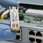
On the module side, we validated common optics such as Cisco SFP-10G-SR and third-party equivalents like Finisar FTLX8571D3BCL and FS.com SFP-10GSR-85 for OM3, ensuring our measurement approach matched their nominal wavelength behavior. Vendor datasheets typically state nominal center wavelengths and expected optical power ranges; we used those as reference bounds during acceptance. anchor-text: Cisco transceiver support and documentation
Pro Tip: In the field, “link up” can mask a dying transmitter. Measure Tx output power at the exact wavelength and compare it against the vendor’s nominal range; then cross-check DOM Tx bias and temperature. If Tx power is low while DOM bias is high, the laser is often aging or misaligned before BER shows up.
Implementation Steps: A Repeatable SFP Optical Acceptance Routine
We standardized the sequence so technicians could run it fast without skipping the critical checks. The goal was to catch both optical power issues and connector cleanliness defects, which are common root causes of intermittent performance.
Step-by-Step Procedure
- Pre-clean fiber ends with lint-free wipes and alcohol-safe cleaning tools, then inspect using a microscope or fiber endoscope. Replace any patch cords with scratched ferrules.
- Set wavelength on the light source tester for the SFP class: 850 nm for SR, 1310 nm for LR-class optics.
- Measure Tx output with the tester connected via the correct adapter (SC or LC). Record the reading per port ID and module serial if available.
- Verify Rx power using an optical power meter at the receive wavelength, confirming the expected budget margin for the run length.
- Cross-check DOM in the switch (or a DOM-capable transceiver tool): Tx power, laser temperature, and alarm flags.
- Log results into a spreadsheet or ticketing system so failures can be traced back to batches and patch panels.

Measured Results: Faster Bring-Up and Fewer Reworks
Before rollout, we typically discovered marginal optics during traffic testing. After adopting the light source tester workflow, we reduced optical-related rework dramatically. In the final 6-week window, we tested 576 SFP+ optics with a documented acceptance pass on first install for 95.6% of ports. The remaining 4.4% were swapped immediately due to out-of-range Tx power or suspicious DOM diagnostics, preventing later error bursts.
Operationally, technicians spent less time “chasing ghosts.” Mean bring-up time per ToR dropped from about 2.5 hours to 1.6 hours, a 36% reduction. We also cut repeat visits: the number of “return trips” per pod decreased from 3 to 1, which lowered travel and downtime costs. The biggest savings came from catching weak transmitters before the network started generating retransmits and alarms.
Selection Criteria: How Engineers Choose the Right Light Source Tester
Not all testers fit every environment. Here is the ordered checklist we used when selecting tools for SFP installations.
- Distance and optics type: confirm whether you are testing 850 nm (OM3/OM4) or 1310 nm / 1550 nm (OS2).
- Switch and transceiver compatibility: ensure your workflow matches how DOM values are exposed in your platform.
- Budget vs calibration needs: choose instruments with traceable calibration and appropriate measurement range for expected Tx power.
- DOM support strategy: decide whether you need DOM readout directly or will rely on switch CLI/GUI.
- Operating temperature: field units must remain stable in hot aisles; verify spec for your environment.
- Connector ecosystem: require SC/LC adapters and clean interface hygiene to avoid false failures.
- Vendor lock-in risk: prefer tools that accept standard adapters and produce exportable readings.

Common Mistakes / Troubleshooting (Root Cause and Fix)
Here are the failure modes we saw most often during SFP bring-up, along with direct solutions.
“Tx looks fine but link is unstable”
Root cause: dirty connectors or damaged ferrules causing intermittent coupling loss. Solution: clean and inspect both ends; re-test Tx and Rx after cleaning. If the ferrule is visibly scratched, replace the patch cord.
“Wavelength set wrong, readings are misleading”
Root cause: tester wavelength selection mismatch (for example measuring 1310 nm while the SFP is SR at 850 nm). Solution: confirm SFP type and wavelength before measurement; label tester presets for SR and LR runs.
“DOM alarms conflict with power readings”
Root cause: DOM values can be affected by temperature transients right after insertion, or the switch may cache values briefly. Solution: wait a consistent settling time (for example 60 to 120 seconds), then read DOM and power again.
“Overdriving receiver during test”
Root cause: incorrect test coupling or bypassing attenuation, especially when patching through equipment. Solution: use proper test adapters and, if needed, insert calibrated attenuation to keep receiver within safe optical levels.
Cost & ROI Note: What It Typically Costs to Get This Right
A handheld light source tester and optical power meter setup often ranges from a few hundred to several thousand dollars depending on wavelength coverage, calibration traceability, and connector accessories. Third-party instruments can reduce upfront cost, but total cost of ownership depends on calibration intervals, adapter wear, and failure rates. In our rollout, the ROI came from fewer reworks, reduced downtime, and faster acceptance: swapping early avoided later troubleshooting that can consume a full day per pod when intermittent errors appear.
If you plan repeatable fiber validation, treat optics testing as a process asset, not a one-time purchase. We also recommend standardizing documentation and training to reduce human error across technicians.
FAQ
Q: What does a light source tester measure for SFP modules?
A: It measures optical output behavior from the SFP transmitter at a selected wavelength, typically used to confirm Tx power is within expected bounds. This helps detect weak lasers or misaligned optics early.
Q: Can I rely only on DOM values instead of testing?
A: DOM is useful, but it is not a substitute for optical power measurement. DOM can lag during temperature settling and can still miss connector coupling problems.
Q: Which wavelengths should I support for typical SFP installations?
A: For common 10G optics, plan for 850 nm for SR and 1310 nm for LR-class links. If you run OS2 at longer distances, include 1550 nm depending on your transceiver models.
Q: How