If you have ever seen a link that negotiates fine but fails under load, the culprit is often jitter and degraded eye openings rather than outright loss. This article helps network engineers and lab technicians run a practical jitter test SFP workflow using eye diagram measurements, explain what the numbers mean, and avoid common measurement traps. You will also get a step-by-step implementation plan, a comparison table of typical SFP test targets, and troubleshooting actions for the top failure modes.
Prerequisites for a reliable jitter test SFP workflow
Before you connect an SFP into a test setup, confirm that your gear can measure at the right electrical/optical interface and that your reference plane is correct. Many “mystery failures” come from probing the wrong point in the chain or using a scope bandwidth that is insufficient for the bit rate. Plan for repeatability: label ports, use fixed attenuators, and log environmental conditions such as temperature and fiber cleanliness.
What you need on the bench
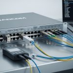
At minimum, you need an SFP under test (DUT), a compliant test environment, and either an eye-diagram capable oscilloscope or a BER/jitter test solution that supports the DUT’s data rate. For optical SFPs, also prepare clean fiber jumpers and (if applicable) an optical attenuator to avoid receiver saturation.
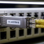
- DUT: SFP or SFP+ module (example: Cisco SFP-10G-SR, Finisar FTLX8571D3BCL, or FS.com SFP-10GSR-85)
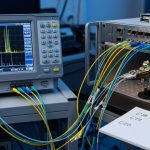
- Test instrument: scope with high-speed sampling and eye-diagram software, or a dedicated jitter analyzer
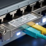
- Optical interface: fiber test harness, stable light source/receiver path, and clean connectors
- Electrical interface: if using a breakout board, ensure controlled impedance and correct termination
- Reference standards: IEEE 802.3 link specifications and vendor datasheet measurement guidance
For timing and eye metrics, IEEE 802.3 defines link behavior and performance expectations for Ethernet physical layers, while vendor datasheets often include recommended test conditions for their optics. Use [Source: IEEE 802.3] as the baseline for required modes and [Source: Vendor datasheets] for jitter/eye measurement context. If you are validating compliance in a formal process, align your method with the test approach described in [Source: ANSI/TIA-568 and relevant fiber handling guidance] for cabling cleanliness and test practices.
- Expected outcome: A bench setup where your measurement reference point is known (transceiver output or receiver input) and your instrument bandwidth supports the DUT bit rate.

Step-by-step implementation: run jitter test SFP with an eye diagram
This numbered plan focuses on practical measurement repeatability. It is written for both electrical and optical test paths, but the critical idea is the same: you measure the eye at the correct reference point and with enough bandwidth so that jitter and inter-symbol interference are faithfully represented.
Identify the link mode and target data rate
Determine whether you are validating 1GBASE-SX, 10GBASE-SR, or another Ethernet physical layer supported by your SFP. Confirm the nominal line rate and encoding requirements from the module datasheet and the relevant Ethernet standard. Then choose instrument settings that match the bit period and expected modulation.
- Expected outcome: You can state the DUT line rate (for example, 10.3125 Gbaud for 10GBASE-SR) and set the oscilloscope time base accordingly.
Establish a clean optical path (or correct electrical reference)
For optical SFPs, inspect fiber end faces and clean if necessary; even microscopic contamination can create intermittent degradation that looks like random jitter. Use a stable fiber harness and keep attenuation within the receiver’s linear range. If using an electrical breakout, verify the board’s trace impedance and ensure proper termination to reduce reflections that can artificially close the eye.
- Expected outcome: A stable optical/electrical connection where the eye diagram does not “wander” due to connector issues.
Configure the instrument for eye capture
Enable eye diagram acquisition and set the acquisition mode to produce a statistically meaningful trace count. Use a sampling rate high enough to avoid under-sampling artifacts, and ensure the bandwidth is sufficient for the DUT’s transition density. If your scope offers a “de-skew” or “trigger alignment” mode, apply it carefully and document the settings.
- Expected outcome: An eye diagram that shows a stable pattern with consistent crossing behavior and no obvious measurement aliasing.
Acquire and export jitter metrics
Most eye-diagram tools compute jitter and eye descriptors such as unit interval (UI), crossing distributions, and sometimes separate components like deterministic jitter (DJ) and random jitter (RJ) depending on the analyzer. Capture at least two runs: one at nominal operating temperature and one after a short thermal soak (for example, 10 to 15 minutes) if your process requires it.
Record metrics that you can compare across modules and across vendors. In field acceptance, engineers often track eye height/width proxies and the measured jitter at a defined threshold crossing point (for example, at 50 percent of the eye amplitude), because those correlate strongly with receiver tolerance.
- Expected outcome: A logged dataset containing eye parameters and jitter metrics with trace settings documented.
Evaluate pass/fail using consistent thresholds
Use the vendor’s recommended test conditions and any compliance targets provided for the module and link. In practice, you will rarely rely on a single number; instead, confirm that the eye opening is adequate and that jitter does not exceed tolerance at the relevant decision threshold. If you are doing internal acceptance, define your own limits based on historical known-good modules and the BER test results that your organization trusts.
Pro Tip: If your jitter test SFP results look “too good” compared to real traffic, check whether you are measuring at the transmitter instead of the receiver. Eye closure often happens after fiber dispersion, connector loss, and any host PCB equalization, so a transmitter-only eye can hide system-level impairment.
- Expected outcome: A decision that ties jitter/eye metrics to receiver tolerance and operational confidence, not just a single snapshot.

Common jitter test SFP targets and how to interpret them
Jitter is not one thing; it is a family of timing variations that can be deterministic (pattern-related) or random (noise-related). Eye diagrams compress this behavior into a visual and measurable opening; the narrower the eye and the more the crossing distribution spreads, the harder it is for the receiver clock and slicer to make correct decisions. The key is to interpret jitter metrics in the context of your sampling, decision threshold, and reference plane.
What metrics are most useful in practice
When engineers review results, they typically focus on eye opening and crossing behavior. Depending on equipment, you may see:
- Eye height (vertical margin) and eye width (timing margin)
- Jitter in UI or in seconds at a specified crossing percentage
- Crossing histogram spread, often mapped to RJ/DJ components
- Deterministic impairment indicators such as periodic jitter patterns
Typical SFP optics and their measurement considerations
Below is a practical comparison of common SFP optical categories and what you should expect to validate during jitter and eye testing. Actual specifications vary by manufacturer and revision, so treat this as a planning reference rather than a compliance claim.
| Module example | Data rate / mode | Nominal wavelength | Typical reach | Connector | Operating temperature | What to watch in jitter test SFP |
|---|---|---|---|---|---|---|
| Cisco SFP-10G-SR | 10GBASE-SR (SFP+) | 850 nm | ~300 m over OM3 | LC | 0 to 70 C (varies by exact SKU) | Eye closure from insufficient optical power, fiber cleanliness, and host equalization mismatch |
| Finisar FTLX8571D3BCL | 10GBASE-SR (SFP+) | 850 nm | ~300 m over OM3 class | LC | -5 to 70 C (check datasheet) | DJ from pattern effects; ensure stable trigger alignment and enough sampling bandwidth |
| FS.com SFP-10GSR-85 | 10GBASE-SR (SFP+) | 850 nm | ~300 m over OM3 class | LC | -40 to 85 C (check exact part) | Thermal drift impact on eye height; verify DOM readings and host compatibility |
For the underlying standards context, consult [Source: IEEE 802.3] for physical layer behavior and tolerance concepts, and [Source: vendor datasheets] for specific measurement conditions and any listed eye/jitter guidance.

Selection criteria checklist for jitter test SFP acceptance
Choosing the right modules and measurement setup is as important as running the test itself. The goal is to minimize false rejects while ensuring that any jitter/eye margin is sufficient for the installed link. Use the checklist below in order, because earlier items often determine whether later measurements are meaningful.
- Distance and fiber type: confirm OM3/OM4/OS2 and expected span length; dispersion and link budget strongly affect eye height.
- Budget and optical power margin: verify that receive power is within the receiver’s linear range; too high can add distortion, too low increases noise-driven jitter.
- Switch and host compatibility: confirm SFP/SFP+ compatibility with your specific switch model and firmware; some hosts apply equalization tuned for known optics.
- DOM support and monitoring policy: ensure the host reads DOM correctly (temperature, bias, TX power, RX power). Log DOM during tests to correlate thermal effects with eye closure.
- Operating temperature and thermal soak plan: test at relevant temperatures; if your site runs hot, include a thermal run.
- Vendor lock-in risk: third-party modules can work, but plan for a compatibility matrix and repeat acceptance tests before scaling.
For formal network assurance, align your decision process with your organization’s acceptance policy and any vendor-specific interoperability notes. If you are using third-party optics, keep a small “known-good” inventory to isolate whether issues are module-specific or system-specific.
Common mistakes and troubleshooting tips for jitter test SFP
Below are the most frequent failure modes seen in the field. Each includes a root cause and an action that typically resolves the issue. Use these as a fast diagnostic tree when eye diagrams look wrong or jitter metrics drift unexpectedly.
Troubleshooting failure point 1: Eye diagram looks closed even with strong signal
Root cause: measurement reference mismatch or under-sampling/insufficient bandwidth. If the scope bandwidth is too low, the transitions smear and the eye appears artificially small.
Solution: verify sampling rate and bandwidth are appropriate for the DUT bit rate; increase bandwidth, adjust acquisition settings, and confirm you are probing at the correct reference plane (receiver side when possible).
Troubleshooting failure point 2: Jitter metrics vary wildly between runs
Root cause: fiber connector contamination, loose patch cords, or unstable trigger alignment. Intermittent reflections or micro-disconnects can create non-repeatable timing artifacts.
Solution: clean connectors, reseat fiber jumpers, replace suspect patch cords, and lock acquisition trigger settings. Record DOM readings during each run to confirm thermal and optical stability.
Troubleshooting failure point 3: Works in the lab, fails in production under load
Root cause: system-level impairment not reproduced in the test: host PCB equalization differences, different fiber routing, patch-panel effects, or oversubscription-induced thermal variation.
Solution: replicate the production topology as closely as possible: include the same switch model/firmware, same patch-panel components, and similar link length. If you can, capture BER under traffic and correlate it with eye/jitter results.
Cost and ROI note for jitter test SFP validation
Typical pricing for SFP/SFP+ optics varies by brand, reach, and temperature grade. In many enterprise environments, 10G SR optics often sit in a rough range of tens to low hundreds of currency units per module, while specialized test equipment (oscilloscopes with high-speed options or jitter analyzers) can cost far more than the optics themselves. The ROI usually comes from reducing field failures and truck rolls: if your organization sees even a small number of intermittent link outages per quarter, tighter jitter/eye acceptance can prevent costly troubleshooting.
Total cost of ownership includes module cost, test labor time, and spares. OEM optics may carry a premium but can reduce compatibility risk; third-party optics can lower purchase price but require a structured acceptance and interoperability validation plan. In practice, teams often amortize test setup time by using “golden” reference modules and running faster verification cycles once the baseline is established.
FAQ
What instrument do I need for a jitter test SFP?
You can use a high-speed oscilloscope with eye-diagram and jitter measurement capabilities, or a dedicated jitter analyzer that supports the DUT’s data rate. The key requirement is sufficient bandwidth and sampling rate so that the eye pattern is not distorted by measurement limits. Always document your acquisition settings for repeatability.
Should I measure jitter at the transmitter or receiver?
For link-quality validation, receiver-side measurement is more representative because it includes system effects such as fiber attenuation, connector reflections, and host equalization behavior. If receiver-side measurement is not feasible, transmitter-side results are still useful, but you should validate with real BER under traffic before assuming system pass.
How do I interpret jitter in UI for an SFP link?
UI (unit interval) converts timing variation into a fraction of the bit period, making it easier to compare across rates. Smaller jitter relative to the UI and a wider eye opening generally indicate better timing margin. Compare results against vendor guidance or your internal acceptance thresholds derived from known-good modules.
Why does my eye look fine in the lab but fail in the network?
Common causes include different fiber routing, patch-panel hardware, connector cleanliness differences, and host firmware or equalization changes. Also check thermal conditions: temperature drift can reduce eye height or alter transmitter bias, increasing jitter under real loads.
Do I need to run DOM checks during jitter test SFP?
Yes. DOM provides temperature and optical power telemetry that helps correlate eye/jitter changes with operating conditions. If DOM shows TX bias drift or RX power near sensitivity limits, you may see jitter increase even when the module is otherwise “working.”
Are third-party SFP modules safe to use for jitter-sensitive links?
They can be safe, but you should treat them as candidates that require interoperability and acceptance testing with your exact switch model and firmware. Build a compatibility matrix and run the same jitter/eye verification workflow for each module batch before scaling deployment.
By following a disciplined jitter test SFP procedure—correct reference plane, clean optical path, bandwidth-appropriate acquisition, and consistent thresholds—you can turn eye diagrams into actionable acceptance criteria. Next, review fiber-optic-transceiver-eye-diagram-basics to connect eye metrics to link budget and real operational risk.
Author bio: I have deployed optical Ethernet links and validated transceiver health in production environments using eye-diagram and jitter measurements under real thermal and cabling conditions. I write field-oriented test procedures that help teams reduce intermittent failures and improve acceptance confidence.