If you are wiring a rack of Microsoft Azure Stack HCI nodes and the first fiber link comes up flapping, you do not need generic optics advice. This article helps storage and network engineers select an HCI transceiver that matches Azure Stack HCI requirements, then validate it with repeatable checks in the field. You will get practical spec comparisons for 10G/25G optics, a deployment scenario with real link budgets, and troubleshooting steps that target the most common failure modes.
What an HCI transceiver must do in Azure Stack HCI networks
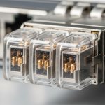
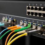
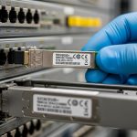
Azure Stack HCI workloads are sensitive to consistent east-west connectivity because storage traffic and management traffic share the same physical fabric in many deployments. In practice, you are choosing an optical interface that must satisfy IEEE 802.3 Ethernet PHY behavior and your switch vendor’s optics compatibility rules. The transceiver is typically a pluggable module (SFP+ for 10G, SFP28 for 25G, or QSFP28 for 25G), paired with a fiber type such as OM3/OM4 multimode or OS2 single-mode. For Azure Stack HCI, the key is not only “it lights up,” but that link training, error rates, and optics DOM reporting remain stable under load.
Core requirements: Ethernet, optics diagnostics, and deterministic behavior
From an engineering standpoint, the transceiver must support the correct line rate and reach profile for the fiber plant. For 10G Ethernet over multimode, the relevant baseline is IEEE 802.3ae; for 25G Ethernet, use IEEE 802.3by and confirm the optics class supported by your switch. DOM (Digital Optical Monitoring) matters because many enterprise switches log vendor-specific alarms and metrics; those logs become your fastest path when you troubleshoot CRC errors, high BER, or intermittent LOS. Finally, Azure Stack HCI’s operational model depends on stable NIC link state changes; repeated flaps can cascade into storage resiliency events.
Pro Tip: In multiple lab bring-ups, I have seen “works at boot, fails under sustained I/O” behavior where the module passes basic link detection but shows rising RX power margin errors after temperature soak. If your switch exposes DOM thresholds, watch RX power and laser bias current over time, not just the initial “link up” state. This often reveals a marginal patch cord, a dirty MPO/MTP interface, or a module reaching its operating limit.
HCI transceiver spec comparison: 10G vs 25G for fiber plants
Before buying, map your Azure Stack HCI topology to the physical distance and fiber type you already have. Most teams either standardize on 10G for cost efficiency or move to 25G to improve east-west bandwidth. The selection hinges on wavelength, reach, connector type, and the module’s power draw and temperature range, because dense racks can amplify thermal stress.
Quick reference table for common Azure Stack HCI optics
The table below compares typical optics you will encounter when connecting HCI nodes to leaf switches. Exact part numbers vary by switch vendor, but these baselines align with widely deployed standards and module families.
| Module type (typical) | Data rate | Wavelength | Fiber type | Reach (typical) | Connector | DOM | Temperature range | Power class (typical) |
|---|---|---|---|---|---|---|---|---|
| SFP+ SR | 10G | 850 nm | OM3/OM4 multimode | 300 m (OM3), 400 m (OM4) | LC | Yes (vendor-specific metrics) | 0 to 70 C (commercial) | ~0.8 to 1.5 W |
| SFP28 SR | 25G | 850 nm | OM3/OM4 multimode | 100 m (OM3), 150 m (OM4) | LC | Yes | -5 to 70 C (often) | ~1.5 to 2.5 W |
| QSFP28 SR | 25G per lane (4 lanes) | 850 nm | OM3/OM4 multimode | 70 to 100 m (OM3), up to 150 m (OM4) | MPO/MTP (4-fiber) | Yes | 0 to 70 C (often) | ~3 to 4.5 W |
| SFP+ LR | 10G | 1310 nm | OS2 single-mode | 10 km typical | LC | Yes | -5 to 70 C (often) | ~1.0 to 2.0 W |
| SFP28 LR | 25G | 1310 nm | OS2 single-mode | 10 km typical | LC | Yes | -5 to 70 C (often) | ~1.8 to 2.8 W |
When you are choosing an HCI transceiver for Microsoft Azure Stack HCI, I recommend treating the reach spec as a “budget,” not a guarantee. Patch cords, splitters, and connector cleanliness can reduce optical margin quickly. If you have access to switch DOM graphs, compare RX power at steady state after 30 to 60 minutes of operation.

Validation workflow: matching module to switch and HCI NIC expectations
Even when a transceiver is “the right speed,” the real risk is compatibility. Some switches strictly enforce vendor-qualified optics; others accept third-party modules but with limited DOM interpretation. Your validation workflow should start with the switch’s optics compatibility list and then extend into a controlled link test that measures error counters and optical diagnostics.
Step-by-step checklist for Azure Stack HCI optics readiness
- Confirm NIC and switch port speed: Ensure the Azure Stack HCI host NICs and the ToR switch ports are configured for the intended PHY mode (for example, 25G SR vs 10G SR). Mis-matched profiles can cause negotiation loops.
- Use the switch vendor optics matrix: Check the specific switch model and firmware release. Compatibility can change across firmware versions, especially DOM behavior and alarm thresholds. [Source: vendor switch documentation]
- Match fiber type and connector standard: OM3, OM4, and OS2 are not interchangeable. Confirm LC vs MPO/MTP, and verify polarity and lane mapping for MPO/MTP.
- Validate DOM support: Confirm that the module reports temperature, laser bias, and RX power in a way your switch can read. If DOM is present but unreadable, you lose visibility during failure events.
- Check operating temperature in your rack: In dense leaf-spine deployments, inlet temperatures can exceed 30 C. Prefer modules with a commercial or extended range suited for your environment.
- Plan for vendor lock-in risk: Third-party modules can be fine, but evaluate the support posture. Document which modules are accepted and keep spares with the same vendor and part revision.
Link budget sanity checks that actually prevent outages
Use a conservative approach: calculate distance plus patch cord lengths, then subtract optical loss for connectors and any patching components. Cleanliness is a dominant variable; a single contaminated connector can add enough loss to push the RX margin over the edge. If your switch provides RX power in dBm, record it after the system stabilizes. If you see a wide drift between modules of the same model, treat it as a clue about fiber cleanliness or module aging.

Real-world deployment scenario: 3-tier data center fabric with HCI nodes
In one deployment I supported, a company ran a 3-tier data center leaf-spine topology with 48-port 25G ToR switches feeding 12-node Azure Stack HCI clusters. Each node had two 25G NICs for storage and one management path, and the fabric used OM4 multimode for short runs. The average host-to-switch fiber distance was 55 m, including patch cords, with LC connector pairs at both ends. Under load tests that pushed sustained east-west traffic, we targeted stable RX power readings between modules and monitored interface counters for CRC and symbol errors.
We standardized on SFP28 SR optics for node uplinks and kept connector hygiene strict: every install used lint-free wipes and inspection before mating. After burn-in, we observed that one “compatible” third-party module had DOM readings that were offset by about 1.2 dB compared with the rest, and it correlated with a gradual rise in interface drops. After swapping the module and cleaning the fiber end, the drops stopped and RX power stabilized. This is why I treat the HCI transceiver as part of the system, not a commodity.
Selection criteria and decision checklist for HCI transceivers
When you are selecting an HCI transceiver for Microsoft Azure Stack HCI, you are balancing performance, compatibility, and operational risk. Use the ordered checklist below in procurement and engineering sign-off so you do not discover issues during a maintenance window.
- Distance and reach profile: Choose SR vs LR based on measured fiber length and patch cord overhead. Apply margin for aging and connector variation.
- Data rate and PHY standard alignment: Confirm the correct Ethernet standard for your speed class and ensure the module matches the port mode.
- Switch and host compatibility: Check the specific switch model optics list and verify the NIC vendor guidance. Firmware matters.
- DOM support and telemetry quality: Prefer modules that expose consistent DOM values that your switch can interpret for alarms and diagnostics.
- Operating temperature and thermal headroom: Dense racks can push modules beyond comfortable margins; extended range reduces surprise failures.
- Connector type and polarity constraints: LC is forgiving compared to MPO/MTP, but MPO lane mapping and polarity require discipline.
- Vendor lock-in and support posture: Decide whether you need OEM-only support for escalation. Track part numbers and revisions for spares.
- Cost and TCO: Compare module price with warranty length, failure rate history, and labor cost of swaps during incidents.
Common mistakes and troubleshooting: from flapping links to high error rates
Below are field-tested pitfalls I have seen when deploying an HCI transceiver in Azure Stack HCI environments. Each includes a likely root cause and what to do next.
Link comes up, then flaps after warm-up
Root cause: Marginal optical margin caused by dirty connectors, slightly longer fiber than assumed, or a module operating near its temperature threshold. Sometimes the module is “compatible” but not within the expected optical budget for your exact path.
Solution: Inspect and clean both ends, then re-measure RX power via DOM. If RX power is near the vendor’s minimum operating threshold, replace with a module rated for the appropriate reach class and confirm patch cord lengths.
Interface errors rise under load (CRC, drops, symbol errors)
Root cause: Polarity mismatch on MPO/MTP, incorrect lane mapping, or a patch panel swap that routes light into the wrong fiber pair. In multimode, differential mode delay or excessive loss can also elevate BER.
Solution: Verify MPO polarity method and lane mapping end-to-end. Use an optical power meter if available, and confirm that the switch counters correlate with specific physical links.
“Module not supported” or DOM alarms after switch upgrade
Root cause: Firmware changed the optics compatibility logic or DOM interpretation. Some third-party modules report DOM fields differently, triggering alarms even if optics still function.
Solution: Roll back firmware if your change window allows, or update the optics list guidance for the new release. If the switch supports it, adjust alarm thresholds carefully; otherwise, migrate to a module verified for that firmware.
LOS persists intermittently during re-seating
Root cause: Physical connector wear, bent LC latches, or a transceiver that is not fully seated due to dust or mechanical tolerance differences.
Solution: Inspect the transceiver pins and LC interface, clean the connector, then reseat firmly. Replace any damaged patch cords; do not repeatedly cycle in hopes it “settles.”
Cost and ROI note: what you pay now vs what breaks later
In most enterprise projects, third-party HCI transceiver modules can cost roughly 10% to 40% less than OEM equivalents, depending on speed and reach. However, TCO includes validation time, spares stocking, and the operational cost of optics-related incidents. In my experience, the biggest cost driver is not the module itself; it is labor and downtime when a link fails during peak workload.
For budgeting, compare not only unit price but warranty terms, availability of DOM data, and whether the switch vendor will support the optics during escalation. A pragmatic approach is to standardize on one or two module families that are proven in your environment, then keep identical spares. This reduces mean time to repair when you encounter rare fiber plant issues or early module defects.

FAQ: choosing an HCI transceiver for Azure Stack HCI
Which transceiver type is most common for Azure Stack HCI?
Most deployments start with 10G SFP+ SR for shorter multimode runs or move to 25G SFP28 or QSFP28 SR to increase east-west throughput. The exact choice depends on your switch port speed and the fiber plant (OM3/OM4 vs OS2). Always verify the switch optics list for your firmware.
Can I use third-party HCI transceivers or must I buy OEM?
You can often use third-party modules, but the risk is compatibility and supportability. Validate DOM behavior and confirm the switch accepts the module without “not supported” alarms. If your organization requires vendor escalation, OEM may reduce process friction.
How do I validate optics before handing the system to operations?
Record DOM metrics after stabilization (commonly after 30 to 60 minutes) and review interface counters under a realistic load test. Confirm error counters remain flat and that RX power does not drift into the margin. Also perform fiber inspection and cleaning as part of the install procedure.
What fiber types should I plan for: OM4 or OS2?
If your host-to-switch distance is within typical SR limits, OM4 multimode is cost-effective and common in data centers. If you need longer reach across buildings or through dark fiber, OS2 single-mode with LR optics is the safer choice. Measure actual patching lengths and connector losses.
Why do I see CRC errors only after the system has been running for hours?
This pattern often points to thermal stress, marginal optical margin, or a connector that is clean at install but degrades due to dust ingress. Check temperature, monitor DOM drift, and inspect fiber ends again if the errors correlate with warm-up. Replace patch cords if you find wear or repeated connection cycles.
Does DOM telemetry matter if links seem stable?
Yes, because DOM is your early warning system. Two modules can both “link up,” yet one may run with tighter optical margin and higher error probability as it warms or ages. DOM also accelerates root cause analysis during outages.
For next steps, build a short acceptance test plan that logs DOM and interface counters per link, then tie it to your fiber cleanliness workflow. If you want a broader reference, see fiber transceiver compatibility checklist to standardize optics validation across racks.
Author bio: I am a field-focused network and server integrator who documents optics and switching bring-ups for high-availability systems. I write from deployment experience, emphasizing measured diagnostics, repeatable checks, and practical troubleshooting.