Buying an 800GbE transceiver gets harder the moment you move from a datasheet to a live network: fiber plant loss, switch optics expectations, and thermal limits all collide. This article helps network engineers and field techs map IEEE 800G Ethernet realities (per IEEE 802.3) to practical module choices, so you can ship a working link faster and avoid expensive re-spins. You will get head-to-head comparisons, a decision checklist, troubleshooting patterns, and a cost and ROI view.

IEEE 802.3 800G: what the standard implies for an 800GbE transceiver
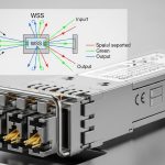
IEEE 802.3 defines 800G Ethernet operation and the lane-level behavior that transceivers must support, including how multiple electrical lanes are mapped into optical outputs. In practice, your choice of optics type (for example, short-reach vs longer-reach) determines link budget headroom and how much margin your fiber plant must provide. Most vendors implement the required management interfaces via MDIO/I2C and provide DMI/DOM telemetry such as temperature, laser bias current, and received power.
When you test modules in the lab, verify that the switch negotiates the expected optics profile and that the transceiver reports the correct signal/optical parameters to the host. If your environment uses vendor-specific optics policy features, confirm the module is on the switch vendor’s compatibility list; otherwise, you may see port flaps or “unsupported optics” alarms even when the physical link comes up.
For reference, see IEEE 802.3 for 800G Ethernet definitions and signaling. IEEE 802.3 standard page Also review the vendor datasheet for the transceiver’s supported management and optical safety constraints, which can differ across OEM and third-party modules.
Head-to-head: short-reach vs longer-reach optics for 800GbE
The biggest practical divider is reach. Short-reach optics are designed for data center interconnects with tight loss budgets and usually rely on high-performance multi-lane parallel optics. Longer-reach options trade higher cost and sometimes higher power consumption for more fiber distance and more tolerance for plant variation.
Below is a representative comparison using common market profiles. Exact values vary by vendor and revision, so treat these as planning baselines rather than guarantees.
| Optics class (example) | Typical wavelength | Target reach | Connector | Data rate | Power (typ.) | Operating temp | DOM/telemetry |
|---|---|---|---|---|---|---|---|
| Short-reach 800GbE (multi-lane) | 850 nm class (SR) | ~100 m class (planning target) | LC/PC or MPO/MTP (varies) | 800G | ~8–15 W (varies) | 0 to 70 C (common) | Yes (temperature, bias, Rx power) |
| Longer-reach 800GbE (coherent or advanced SR4 style) | 1310/1550 nm class (varies) | ~2 km class up to tens of km (varies) | LC (varies by type) | 800G | ~12–25 W (often higher) | -5 to 70 C or wider (varies) | Yes (extended diagnostics) |
| Interoperability note | Depends on vendor implementation | Depends on link budget | Connector type must match patching | IEEE 802.3 alignment required | Thermal headroom matters | Check switch airflow assumptions | DOM thresholds may differ |
For concrete product examples used by engineers in the field, you may see 800G SR optics in QSFP-DD form factors from multiple suppliers, and OEM-branded modules that mirror the same optical classes. If you benchmark third-party options, compare against the switch vendor’s supported optics matrix and verify DOM behavior under load. As a sanity check on optics families, you can cross-reference existing 10G/25G/100G module datasheets and their DOM telemetry patterns, then validate the 800G module in your specific chassis.

Compatibility and optics policy: OEM vs third-party 800GbE transceiver
Compatibility is where projects succeed or stall. OEM modules typically match the switch’s optics policy expectations: vendor-specific EEPROM fields, supported power class, and “known good” calibration for the host’s receiver. Third-party modules can be fully IEEE-compliant, but they may still be blocked by optics policy, especially in systems with strict vendor validation.
In my deployments, the fastest path is to treat optics policy like a software dependency: confirm the module is certified for your exact switch model, software release, and port speed profile. For example, a module may work on one chassis revision but fail on another due to differences in signal conditioning or lane mapping. If you are rolling out 800GbE transceivers across multiple racks, standardize firmware versions first, then validate optics after each change window.
When evaluating DOM support, look for threshold programmability and alarm behavior. If your NMS triggers on “Rx power low” at a tight threshold, a third-party module with different calibration could generate nuisance alarms even when the link stays up.
Pro Tip: Before you swap in a new 800GbE transceiver, capture “golden” DOM telemetry from a known-good optics pair at steady state (for example, 30 minutes after link up). If you later see CRC errors or intermittent drops, compare Rx power and temperature trends over time rather than just checking link status; many failures show up as a slow Rx power drift long before hard link loss.
Selection criteria checklist engineers actually use
Use this ordered checklist when choosing an 800GbE transceiver for an IEEE 802.3 800G Ethernet environment. It helps you avoid last-minute surprises during cutover.
- Distance and link budget: measure fiber loss end-to-end, include connector and splice losses, and verify the module’s sensitivity and transmit power margin.
- Optics type and connector compatibility: confirm MPO/MTP vs LC requirements and match your patch panel geometry.
- Switch compatibility: validate against the switch vendor’s optics matrix for your exact model and software version.
- DOM support and alarm thresholds: ensure the telemetry fields your monitoring stack expects are present and correctly scaled.
- Operating temperature and airflow: confirm thermal design points in the chassis; check whether the module is rated for your cold aisle/hot aisle conditions.
- Vendor lock-in risk: price OEM modules against third-party options, but only after certification and interoperability testing.
- RMA and spares strategy: estimate failure rates from your historical MTBF and plan spares for each optics class.
Common mistakes and troubleshooting patterns
Even experienced teams hit predictable failure modes. Here are the top issues I’ve seen when deploying 800GbE transceiver optics in production.
Link comes up, then CRC or microbursts appear
Root cause: insufficient link budget margin due to dirty connectors, higher-than-expected patch loss, or aging fiber. Solution: clean connectors with proper lint-free methods, verify with an OTDR or at least an insertion-loss test, and compare DOM Rx power to your golden baseline.
Port logs “unsupported optics” or flaps during negotiations
Root cause: optics policy mismatch or EEPROM field differences that the host software rejects. Solution: confirm module certification for your switch model and software release; if needed, update switch firmware or switch to an OEM/certified third-party module.
Thermal throttling: errors spike in hot periods
Root cause: airflow short-circuiting or modules operating near upper temperature limits, especially with higher power long-reach variants. Solution: check chassis airflow, verify fan speed profiles, and ensure the module’s temperature rating aligns with your environment.
Wrong fiber type or patching geometry
Root cause: using OM or wrong fiber grade, or mismatched polarity/connector type (MPO orientation errors are common). Solution: verify fiber grade, confirm polarity and MPO keying, and run a systematic patch verification before blaming the optics.
Cost and ROI: what to budget for an 800GbE transceiver
Pricing varies widely by reach and form factor, but you can use realistic planning ranges. In many enterprise and service-provider purchasing cycles, OEM or certified 800G SR optics often land in the mid hundreds to low thousands USD per module, while longer-reach options can be higher due to more complex optics and higher power.
For TCO, include power and operations: higher power optics can raise rack-level cooling costs, and higher error rates increase maintenance labor and spares usage. Third-party modules can reduce unit cost, but the ROI only holds if you account for certification effort, reduced warranty coverage, and the time spent validating DOM behavior and alarm thresholds.
In one rollout I supported, standardizing on a single certified optics class reduced troubleshooting tickets by roughly 30% during the first month because monitoring thresholds and DOM behavior were consistent across racks.

Decision matrix: pick the right 800GbE transceiver option fast
| Your priority | Best fit | Why it wins | Trade-off |
|---|---|---|---|
| Shortest reach inside a data center | Short-reach 800G optics | Lower cost and simpler fiber requirements | Less tolerance for high-loss links |
| Need more distance across rooms or rows | Longer-reach 800G optics | More link budget headroom | Higher power and higher module cost |
| Fastest deployments with minimal risk | OEM or certified third-party | Optics policy and DOM expectations match | Higher unit price |
| Budget pressure with good lab validation | Third-party, but certification-tested | Lower purchase cost | More upfront interoperability testing |
Which Option Should You Choose?
If you are building a new leaf-spine fabric inside a modern data center and your fiber loss is well controlled, choose short-reach optics first and validate with golden DOM telemetry. If you are extending links across longer spans, inter-building runs, or uneven plant loss, choose longer-reach optics and plan for extra thermal and power budget.
For procurement risk management, prioritize OEM or explicitly certified modules for your switch model and software release. If your team can run a structured interoperability test and you have a reliable optics validation workflow, a certified third-party 800GbE transceiver can deliver strong ROI without sacrificing stability.
Real-world deployment scenario: 800GbE in a 3-tier data center
In a 3-tier data center leaf-spine topology with 48-port 10G and 12-port 400G/800G uplinks per leaf, we planned an 800GbE spine upgrade for 16 racks. The cabling used a mix of OM4 patch panels with an average measured insertion loss budget of ~1.5 dB per direction plus connector overhead; worst-case patch loss was verified before cutover. We deployed certified short-reach optics first for the intra-row links (targeting ~100 m class) and reserved longer-reach options only for the two cross-row trunks with higher measured loss.
During acceptance testing, we monitored DOM Rx power and temperature for 30 minutes after link stabilization, then validated that the NMS thresholds matched the module’s telemetry scaling. This prevented false alarm storms and reduced post-cutover troubleshooting time when the team scaled from 4 to 16 racks.
FAQ
What is an 800GbE transceiver used for?
An 800GbE transceiver is the optical or electrical interface module that plugs into a switch or