In modern data centers, the cooling plan can quietly become the reliability plan. If you run immersion cooling and still treat SFP optics like they live in air, you may be inviting early aging, flaky DOM readings, or link instability. This article helps network and facilities teams evaluate immersion cooling SFP modules by mapping thermal behavior to optical and electrical limits, then giving a practical selection checklist and troubleshooting playbook.
Why immersion cooling changes the SFP thermal story

Most SFP modules are characterized for air-cooled environments where heat leaves the package primarily through convection and conduction to a chassis. In immersion cooling, the surrounding medium changes the dominant heat transfer path: instead of relying on airflow, you get more uniform contact-area heat removal, often with higher effective heat transfer coefficients. That sounds like a win, but it also shifts internal temperature gradients and can alter how the module’s thermal control loop behaves.
Inside an SFP, the key heat sources are the laser driver, receiver front end, clocking/retiming electronics, and sometimes the DSP or signal conditioning ASIC. The module’s optical performance is temperature sensitive because the laser wavelength and receiver sensitivity drift with temperature. Vendors typically specify optical compliance (for example, IEEE 802.3 link budgets and relevant SFF standards) under defined temperature ranges; immersion cooling can keep parts cooler than expected, or keep them cooler in a different spatial pattern than the vendor assumed.
Also, immersion introduces new system-level variables: dielectric properties of the coolant, fluid ingress risk, and how the module is seated thermally against the cage. If the SFP is not designed for the coolant type and contact conditions, you can see accelerated corrosion, altered mechanical tolerances, or adhesive and seal degradation over time.
Thermal impact: what to measure and what to expect
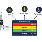
To avoid “it links on day one, then it gets moody” failures, measure the right things during commissioning. Most SFPs expose internal diagnostics via DOM (Digital Optical Monitoring), including laser bias current, received optical power, and temperature. In immersion cooling, you want to compare DOM temperature trends against the chassis and transceiver placement assumptions, not just against ambient room temperature.
Commissioning measurements that actually correlate
- DOM temperature stability: log temperature every 30 seconds for at least 4 hours under steady traffic, then repeat after thermal soak.
- Tx bias and Rx power drift: watch for bias current creep and Rx power movement at constant attenuation.
- BER under stress: run a traffic profile that mimics peak utilization (for example, 64-byte frames at line rate for the target speed) and capture error counters.
- Connector and cage contact: use a thermal camera or IR measurement through the cage window (if available) to verify the heat path is not bottlenecked by mechanical pressure.
Typical optical specs and temperature ranges you must respect
Optical modules are usually binned by temperature range and optical class. For example, a common class is industrial or extended temperature operation, but the exact range depends on the vendor and part number. You should treat the vendor’s specified operating temperature and optical compliance conditions as contractual requirements, even if immersion cooling appears to “cool everything.”
| Specification | What to check | Why it matters in immersion |
|---|---|---|
| Wavelength | 850 nm (SR) vs 1310 nm (LR) vs 1550 nm (ER) | Different thermal sensitivity and dispersion penalties; wavelength drift affects link margin. |
| Data rate | 1G, 10G, 25G, 40G, 100G (varies by form factor) | Higher speed increases heat density and can stress thermal control loops. |
| Reach | For example, 10G-SR is typically up to ~300 m on OM3 fiber (per vendor) | Immersion cooling does not fix link budget; thermal effects can still shrink margin. |
| DOM support | Tx bias current, Rx power, module temperature | DOM readings are your only practical internal telemetry for thermal correlation. |
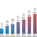
| Connector | LC duplex for fiber transceivers | Fluid exposure and mechanical seating affect optical coupling stability. |
| Operating temp range | Vendor specified module operating range | Immersion may shift gradients; you still must remain inside the spec window. |
| Power consumption | Typical SFP power varies by speed and vendor | Thermal load affects local hot spots and can change reliability curves. |
Pro Tip: During immersion cooling commissioning, compare DOM temperature to link error counters at the same timestamp. If you only look at temperature and ignore BER, you can miss the real failure mode: optical power drift driven by laser bias changes rather than temperature alone.
Choosing an immersion-cooled SFP: practical decision checklist
Selection is where you prevent future pain. Engineers often buy optics first and “verify later,” but immersion cooling deserves a more disciplined approach because the coolant and mechanical seating conditions can differ from the vendor’s test setup. Use this ordered checklist before you authorize deployment.
- Distance and link budget: confirm fiber type (OM3/OM4/OS2), attenuation, connector loss, and expected worst-case margins. IEEE 802.3 compliance does not guarantee your exact installed margin.
- Switch compatibility: validate the SFP vendor and part number against your switch platform’s optics compatibility list. Some platforms enforce vendor-specific EEPROM behaviors.
- DOM and monitoring behavior: confirm DOM thresholds and calibration support. If the switch expects certain alarm ranges, mismatches can trigger false alarms.
- Operating temperature and derating: verify the module’s specified operating range and power dissipation limits. Don’t assume “cooler is always better.”
- Coolant contact and materials: confirm the vendor’s stance on immersion media compatibility, including seals, coatings, and mechanical tolerances. If the vendor is silent, treat it as a risk.
- Vendor lock-in risk: weigh OEM optics (often tighter compatibility) against third-party optics (often cheaper, sometimes less consistent DOM behavior). Plan for a qualification run per optics family.
- Reliability and warranty terms: look for warranty coverage that matches your operational lifecycle and any temperature stress conditions.
Concrete examples of parts engineers commonly validate
In real deployments, teams often test multiple optics families before standardizing. For instance, 10G SFP-SR options from major vendors include parts such as Finisar FTLX8571D3BCL and Cisco SFP-10G-SR, plus third-party equivalents like FS.com SFP-10GSR-85 (exact specs vary by revision). For 25G and beyond, the form factor may shift, but the immersion cooling lessons remain: validate temperature telemetry, DOM behavior, and link stability under your coolant and seating conditions.
That image is the vibe: you want to see where heat actually lands, not where marketing says it should go.
Compatibility and electrical/optical limits you cannot ignore
Even when temperature looks “fine,” electrical and optical interfaces can still betray you. SFP modules use defined electrical signaling and optical parameters that must meet the host’s expectations. In immersion cooling environments, the host board and cage temperature can change, which can shift impedance characteristics, oscillator stability, and signal integrity margins.
On the optical side, the key constraints are transmitter wavelength accuracy, spectral width, receiver sensitivity, and the resulting link budget. On the electrical side, watch for host compliance with the SFP electrical interface and any platform-specific calibration routines. If your switch periodically reads DOM and applies thresholds or resets optics under alarm conditions, you can get link flaps that look like “temperature problems” but are actually “monitoring logic problems.”
Standards and credible references to anchor your expectations
- IEEE 802.3 Ethernet physical layer specifications, which define optical link behavior and compliance concepts. [Source: IEEE 802.3]
- Vendor datasheets for specific transceiver part numbers, including DOM and temperature operating ranges. [Source: Cisco, Finisar, and SFF vendor datasheets]
- ANSI/TIA fiber cabling and optical performance guidance for installed link budgets and attenuation assumptions. [Source: ANSI/TIA-568 series]
When you read vendor datasheets, treat the “tested conditions” section as the chef’s note. If immersion cooling is not included, you must validate anyway.
Yes, it is slightly dramatic. No, it is not optional.
Common mistakes and troubleshooting tips in immersion deployments
Immersion cooling can be excellent, but the failure modes are specific. Here are real, field-relevant pitfalls and how to fix them without sacrificing weekends to the optics gods.
DOM temperature looks stable, but link errors spike
Root cause: laser bias drift or receiver sensitivity drift can occur even with stable temperature if the thermal gradient changes or if the optical coupling changes due to mechanical seating pressure. DOM temperature alone may not capture the internal laser operating point.
Solution: correlate DOM Tx bias current and Rx power with BER/error counters. If Tx bias trends upward while temperature is flat, suspect optical alignment or thermal gradient changes at the package level.
False alarms and optics resets under coolant
Root cause: the host may interpret DOM thresholds differently across vendor part numbers or EEPROM revisions. Immersion can change how quickly temperature reaches equilibrium, causing transient DOM readings that trip alarms.
Solution: update platform optics configuration if supported, and run a soak test to ensure alarm thresholds are not overly tight. Validate that module EEPROM fields match what the switch expects.
Corrosion or seal degradation after coolant exposure
Root cause: the module’s materials and sealing may not be compatible with the coolant chemistry or additives. Even if the optics still “work,” long-term reliability can suffer from corrosion at interfaces.
Solution: require vendor written compatibility guidance for the specific coolant family, and start with a pilot batch. Inspect failed units with microscopy for residue or corrosion patterns and trace them back to coolant exposure assumptions.
Link budget collapse due to connector and fluid effects
Root cause: fluid exposure and handling can degrade connector cleanliness. Immersion does not magically erase contamination. Increased insertion loss shrinks margin, and thermal drift makes the problem worse.
Solution: enforce connector cleaning verification (for example, inspection with a scope) and measure optical power after installation. Maintain a strict handling protocol for LC connectors during immersion retrofits.
This style is for the “teach the team in five minutes” moment.
Cost and ROI: what you save, what you risk, and how to budget TCO
Immersion-ready optics can cost more than standard air-qualified modules, especially when you buy OEM. In typical procurement scenarios, you might see OEM 10G optics priced in the tens of dollars to low hundreds per module depending on reach and brand, while third-party optics often undercut that by a noticeable margin. The real cost is not just the purchase price; it is qualification time, spares strategy, and failure replacement overhead.
From a TCO angle, consider power and cooling efficiency. If immersion cooling reduces fan power and airflow complexity, total facility energy can drop, but your optics must still meet reliability targets. A higher module failure rate can erase savings fast: the cost of truck rolls, downtime, and emergency replacements dwarfs the initial unit price delta.
Plan for a qualification run per optics family and per switch platform. If you run a pilot with, say, 20 to 50 modules and validate temperature telemetry plus BER stability over a full thermal soak window, you reduce the odds of a fleet-wide surprise.
FAQ: immersion cooling SFP questions engineers actually ask
Do immersion cooling SFP modules need special firmware or switch support?
Usually no, but the host platform may apply different DOM alarm thresholds or calibration routines based on EEPROM fields. Validate with your exact switch model and firmware revision, and confirm DOM alarm behavior during thermal soak. [Source: vendor switch and transceiver datasheets]
Is cooler always better for an immersion cooling SFP?
Not necessarily. Optical performance and internal operating points depend on temperature gradients and how the laser driver responds. If immersion changes gradients, you can see bias drift even when overall temperature looks stable. That is why correlating DOM and BER matters.
Can I use any third-party SFP in immersion cooling?
You can try, but treat it as a qualification project, not a plug-and-pray purchase. Third-party optics may differ in EEPROM fields, DOM calibration, and material choices. If the vendor does not provide immersion coolant compatibility guidance, the risk increases.
What diagnostics should I monitor during deployment?
Monitor DOM temperature, Tx bias current, and Rx received power, then correlate them with link error counters or BER measurements. Use a traffic generator that stresses the link in a way similar to your real workload. Do this before you declare the deployment “done.”
How do I validate connector and fiber cleanliness in immersion systems?
Use connector inspection scopes and clean with an approved workflow before installation. After installation, measure optical power and verify link margins under worst-case attenuation. Don’t assume immersion fluid keeps connectors pristine; contamination still increases insertion loss.
Where should I start if I need an immersion cooling SFP recommendation?
Start with your switch platform compatibility list and pick candidate optics part numbers. Then run a pilot batch under your actual coolant and seating conditions, collecting DOM and BER data over thermal soak. Only after that should you standardize your BOM.
If you want fewer late-night callouts, treat immersion cooling as a thermal and monitoring system, not just a cooling trick. Next step: review a compatible transceiver strategy via optical transceiver selection checklist.
Author bio: I have deployed fiber and optics diagnostics in production networks, chasing thermal and DOM edge cases with real BER logs. I write from the bench: lab measurements, vendor datasheets, and field troubleshooting notes that keep links stable.