Your switch may say “link up,” but your optics can still be slowly cooking themselves into packet loss. This article helps data center engineers, field techs, and network planners understand transceiver thermal cooling—what really drives temperature, how it impacts reach and error rates, and how to choose modules that won’t turn your rack into a toaster oven. You will get practical selection criteria, common failure modes, and deployment guidance for real hardware.
Why thermal cooling decides whether your optics behave or misbehave
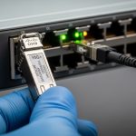
High-speed transceivers convert electrical signals into optical light using lasers and sensitive photodiodes. When internal temperature rises, laser output power, wavelength stability, and receiver sensitivity can drift, which can raise BER and trigger link renegotiation or CRC errors. Modern pluggables (SFP, SFP28, QSFP, QSFP28, QSFP-DD, and OSFP families) rely on a mix of optical power control and thermal design to keep devices within spec. IEEE 802.3 defines Ethernet physical-layer behavior, while vendor datasheets define operating temperature and thermal performance limits; ignoring those limits is like driving with the check-engine light taped over.
What “cooling” actually means inside a pluggable
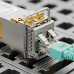
“Transceiver thermal cooling” is not one magic heatsink. It is a system: module case temperature, airflow across the cage, contact pressure to the host, and heat transfer through the PCB and metal shell. Most failures are not dramatic “it died” events; they are gradual performance degradation—laser bias changes, increased jitter, and receiver noise that creeps up as temperature climbs. In practice, you will see symptoms like higher FEC correction counts, intermittent LOS, or sudden BER spikes during hot-aisle days.
To anchor the physics: optical transceivers commonly specify a maximum operating temperature (for example 70C, 85C, or 95C depending on class) and a storage temperature range. Cooling design targets the module case temperature, not just ambient room temperature. If your rack inlet is 30C but your module is buried behind a partially blocked airflow path, your “ambient” becomes an optimistic lie.

Key specifications that govern transceiver thermal cooling
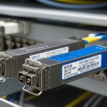
Before you compare part numbers, compare thermal-relevant specs: operating temperature class, maximum case temperature (if provided), power dissipation, and airflow requirements implied by the host platform. Many vendors publish Tx optical power and receiver sensitivity separately from thermal details, but temperature affects both. For selection work, treat power dissipation and temperature class as the “load” your cooling system must carry.
Spec comparison table: typical optics with different thermal profiles
The table below is representative of common enterprise and data center pluggables. Always confirm exact values in the specific datasheet for the exact model and host compatibility.
| Module example | Data rate / Form factor | Wavelength (typ.) | Reach (typ.) | Connector | Operating temp (typ.) | Typical power (typ.) | Cooling relevance |
|---|---|---|---|---|---|---|---|
| Cisco SFP-10G-SR | 10G / SFP+ | 850 nm | ~300 m OM3 (varies) | LC | 0C to 70C (platform dependent) | ~1 to 1.5 W | Airflow matters in high-density chassis |
| Finisar FTLX8571D3BCL | 10G / SFP+ | 850 nm | ~300 m OM3 (varies) | LC | -5C to 70C (varies by grade) | ~1 to 1.7 W | Thermal throttling risk if airflow is blocked |
| FS.com SFP-10GSR-85 | 10G / SFP+ | 850 nm | ~300 m OM3 (varies) | LC | 0C to 70C or 0C to 85C (check grade) | ~1 to 1.8 W | Choose grade aligned to chassis thermal budget |
| Typical QSFP28 LR4 | 100G / QSFP28 | ~1310 nm | ~10 km (varies) | LC (2-fiber or 8-fiber depending) | 0C to 70C (often) | ~3 to 4.5 W | Higher heat per port; airflow and fan curves matter |
| Typical QSFP-DD 200G/400G | 200G or 400G / QSFP-DD or OSFP | 850/1310/1550 nm (family dependent) | Short or long reach | Varies | 0C to 70C or 0C to 85C (check) | ~8 to 15 W | Thermal cooling becomes design-limiting at density |
Notice the pattern: as data rate rises, power dissipation usually rises too. That means thermal cooling becomes less optional in high-density leaf-spine deployments. If your chassis supports 48 ports of 100G and you run them near max optical power, the thermal load is not theoretical; it is a measurable system constraint.
How to pick transceivers that fit your cooling reality
Selection is where engineers earn their coffee. Do not only pick by reach and price; pick by thermal compatibility with your host platform’s airflow and temperature control strategy. The goal is to keep the module within its allowed operating temperature envelope under worst-case fan speeds, blocked vents, and seasonal ambient changes.
Ordered decision checklist engineers actually use
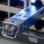
- Distance and optical budget: confirm reach for your fiber type (OM3/OM4/OS2) and transceiver wavelength (850 nm vs 1310/1550 nm). Thermal issues amplify borderline optical margins.
- Host switch compatibility: verify the transceiver is supported in your exact model and software release; some hosts enforce EEPROM/DOM behavior and thermal thresholds.
- DOM support and telemetry: confirm whether you get temperature, laser bias, Tx power, and Rx power via digital monitoring; use it for early warning instead of post-mortem archaeology.
- Operating temperature class: match the module grade to the chassis inlet and expected hotspot conditions; do not assume 70C module grade is safe in a cramped high-density cage.
- Power dissipation and density: estimate total heat load per slot; QSFP-DD and OSFP can be an order of magnitude higher than SFP+.
- Operating airflow strategy: confirm vendor guidance for fan tray modes and airflow direction; blocked intake filters can turn “planned cooling” into “fan cosplay.”
- Vendor lock-in risk: weigh OEM vs third-party; check DOM interoperability and whether the vendor provides a clear compatibility matrix.
Pro Tip: In the field, the fastest way to predict transceiver thermal cooling trouble is to chart module temperature telemetry against fan mode and inlet temperature. If temperature rises faster than inlet by more than a few degrees during fan drops, you likely have localized airflow blockage or insufficient cage-to-air contact.
Common mistakes and troubleshooting for thermal cooling failures
Thermal problems rarely announce themselves politely. Here are concrete failure modes you can recognize, with root causes and fixes.
“Link flaps only on hot days”
Root cause: Ambient inlet temperature rises seasonally or during fan maintenance, pushing the transceiver case temperature beyond its comfortable range. Laser output and receiver sensitivity drift, raising BER until errors exceed the host’s correction capability.
Solution: Verify inlet and module temperatures using DOM. Compare readings against the transceiver datasheet operating range. Then adjust fan profile, clear blocked vents, and validate that airflow baffles are installed correctly.
“Works in one switch but not another”
Root cause: Mechanical fit and thermal transfer differ between platforms; host cages may apply different contact pressure or airflow patterns. Some optics also have DOM thresholds that the host interprets differently.
Solution: Confirm platform compatibility lists from the transceiver vendor and the switch vendor. If you must test a new module, do it in a controlled thermal environment and monitor DOM temperature and Tx/Rx power over a 24 to 72 hour period.
“We see elevated FEC correction counts, then LOS”
Root cause: A marginal optical path (dirty connectors, fiber microbends, or overstressed launch conditions) combined with rising temperature. As temperature increases, the margin collapses faster than you expect.
Solution: Clean connectors with approved procedures, inspect fiber with a scope, and re-check optical power levels. If the module has temperature telemetry, correlate correction counts with temperature spikes to confirm thermal contribution.
“Third-party modules are cheap and then mysteriously expensive”
Root cause: Different thermal design targets and sometimes different DOM behavior. You may end up with modules that meet electrical specs but do not meet your chassis thermal expectations at density.
Solution: Use a compatibility matrix approach: require the vendor to provide tested host models and DOM behavior. Track failure rates by lot number; if a lot shows higher temperature excursions, stop using it and escalate.

Cost and ROI: what thermal cooling changes in your budget
Thermal-aware transceivers can cost more upfront, but the ROI is usually about reduced downtime and fewer truck rolls. In many environments, OEM optics may run roughly $200 to $600 per 10G-class module and $600 to $3,000 per 100G-class depending on reach and grade; third-party can be lower, but only if compatibility and thermal behavior are proven. Total cost of ownership (TCO) should include failure handling, replacements, and the operational overhead of troubleshooting intermittent thermal events.
Power also matters. A 100G QSFP28 class module might dissipate several watts; at 48 or 96 ports, the cumulative heat can influence fan power and cooling infrastructure usage. If thermal cooling is insufficient, you may also see increased fan wear and faster maintenance cycles—an invisible tax that accountants only discover when the cooling budget starts crying.
FAQ
What is transceiver thermal cooling, in practical terms?
It is the complete heat-removal pathway: module case temperature, metal shell conduction, host cage contact pressure, and airflow across the port area. You manage it through correct module temperature grades and ensuring the chassis airflow path is unobstructed.
How do I know if my optics are overheating?
Use DOM telemetry for temperature and correlate it with inlet temperature and fan mode. If you see temperature excursions near the module’s upper operating limit, and errors increase at the same time, overheating is the likely culprit.
Do I need OEM optics for better thermal performance?
Not always, but you do need verified compatibility and documented thermal behavior for your exact host model. Third-party optics can work well when vendors provide tested results and consistent DOM support.
Can dirty fiber look like a thermal problem?
Yes. Dirty connectors reduce optical margin, and thermal drift can then push the link over the edge, making the symptoms appear “temperature-driven.” Clean and scope the fiber first, then confirm thermal telemetry correlation.
What operating temperature should I plan for in a data center?
Plan using your facility inlet targets and worst-case conditions during fan maintenance or seasonal peaks. Then ensure module operating temperature grade provides margin; do not design for “average day” conditions only.
What is the fastest troubleshooting workflow for thermal cooling issues?
Pull DOM temperature, Tx power, Rx power, and error counters, then correlate them with fan mode and inlet temperature. Next, inspect airflow paths, airflow baffles, and port obstructions, and finally validate optics cleanliness and fiber health.
Thermal cooling is the unglamorous hero of high-speed optics: it protects link margin, stabilizes laser behavior, and prevents intermittent failures that waste weekends. If you want the next step, compare module form factors and compatibility using transceiver compatibility matrix.
Author bio: I design network hardware user experiences and validate thermal behavior with real switch and optics deployments, including DOM telemetry and airflow verification. I also enjoy translating datasheet fine print into decisions that field teams can execute without summoning the ghost of downtime.