In dense racks, a single dirty or poorly polished ferrule end can turn a “green” link into intermittent errors. This guide helps network engineers and field technicians use ferrule end face inspection to protect the SFP loss budget for 1G, 10G, and higher optics. You will get practical checks, a spec comparison table, and troubleshooting steps tied to measurable failure modes.
Why ferrule end face inspection changes your SFP loss budget

SFP optical budgets are usually calculated for fiber attenuation plus connector and splice losses. However, end-face contamination and polishing defects add extra insertion loss and can increase return loss, raising BER under marginal power. In practice, a microscopic scratch or film residue can create scatter that behaves like additional dB of loss—often enough to breach the margin built into the link budget.
Field teams typically verify end quality using a fiber inspection scope (typically 200x to 400x magnification) and then correlate results with optical measurements. On-site, technicians often combine scope images with DOM telemetry (if supported) and link counters to confirm whether the issue is optical power, reflectance, or contamination.
What to look for on the ferrule end face
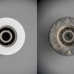
When performing ferrule end face inspection, focus on repeatable categories that map to optical penalties:
- Dust or lint: bright flakes or dark specks near the core region; causes scatter and localized loss.
- Film residue: hazy veil across the glass; often worse than single dust particles.
- Chips or cracks: visible edge damage; can create sharp scattering and unstable coupling.
- Polish scratches: long lines or arcs; can increase backscatter and degrade signal quality.
- Ferrule geometry issues: tilt, end-face non-flatness, or epoxy contamination at the interface.
Pro Tip: If your scope shows a “clean-looking” center but the ferrule edge has a thin film, you can still see rising receiver error counters after a temperature cycle. End-face residue expands and shifts optical coupling, so re-cleaning plus re-inspection often beats swapping optics first.
Inspection-to-spec workflow: from scope image to loss margin
A reliable workflow connects what you see on the end face to what the SFP link is experiencing. Start by confirming the optics and link type (wavelength and reach), then verify that the measured power and error counters align with the budget after cleaning.
Step-by-step field workflow
- Identify the SFP and fiber type: record model, wavelength (for example 850 nm OM3/OM4 vs 1310 nm), and connector type (LC is most common).
- Confirm link budget inputs: count connectors, splices, and patch cords; include manufacturer-rated connector loss values.
- Inspect both ends: check transmit and receive ferrules on each link segment, not only one side.
- Clean correctly: use lint-free wipes and approved cleaning solutions; for stubborn residue, use appropriate cleaning cartridges.
- Re-inspect: take before/after scope images and verify the center and edges are free of films, chips, and scratches.
- Validate with measurements: check SFP DOM (Rx power, alarm thresholds if exposed) and verify link stability and error counters.
Key specs that interact with end-face quality
Even when the fiber and SFP model match the nominal reach, end-face defects can consume margin. The most sensitive links are those operating near the edge of reach, where a few extra dB matter. This is common in high-density data centers with frequent moves, adds, and changes.
| Parameter | Typical 10G Short-Reach SFP+ | Typical 10G Long-Reach SFP+ |
|---|---|---|
| Data rate | 10.3125 Gb/s (10GBASE-SR) | 10.3125 Gb/s (10GBASE-LR) |
| Wavelength | 850 nm (multimode) | 1310 nm (single-mode) |
| Connector | LC/SC (varies by cage and patch panel) | LC/SC (varies) |
| Reach (typical) | 300 m on OM3, up to 400 m on OM4 | 10 km (single-mode) |
| Operating temperature | Often 0 to 70 C (commercial) | Often -5 to 70 C or wider (varies) |
| Why inspection matters | Short reach has less margin; end scatter can dominate | Long reach has more fiber budget, but reflectance issues still hurt |
| Where DOM helps | Rx power alarms and bias stability | Rx power plus error counters correlate with contamination |
Use the scope to capture a reference image before cleaning. Then repeat the inspection after cleaning to confirm the defect category is removed, not merely hidden by glare.
Common SFP link types and where end-face defects hurt most
Different SFP standards tolerate different margins. In multimode 850 nm links, the connector and patch cord losses are a larger fraction of the total budget. In single-mode 1310 nm links, return loss and reflectance can still cause receiver sensitivity issues, especially when connectors are mismatched or improperly seated.
Multimode 10GBASE-SR sensitivity
For 10GBASE-SR SFP+ modules, connectors, patch cords, and splices consume budget quickly. A typical real-world path might include multiple LC connectors and two patch cords. If a patch panel is reworked and ends are not re-inspected, end-face contamination can push the link into a marginal zone where errors appear after thermal cycling.
Single-mode 10GBASE-LR tolerance limits
Single-mode links often have more fiber budget, but end-face problems still show up as higher backscatter and reduced effective coupling. If you see intermittent link flaps, confirm both ends are clean and check connector geometry, including ferrule height and proper latching. Also verify that the SFP is within its specified temperature range and not operating at the edge of compliance.
Think of the end face as an optical element: contamination increases scattering, while scratches and chips change coupling efficiency and reflectance.
Selection criteria checklist: choosing the right inspection and optics approach
Engineers do not choose inspection tools in isolation; they align inspection capability with the optics and connector ecosystem. Use this checklist when planning a rollout or troubleshooting recurring SFP issues.
- Distance and budget headroom: shorter-reach multimode links need tighter end-face control due to smaller margin.
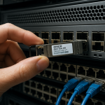
- Switch and cage compatibility: confirm the SFP form factor fits (SFP+ vs SFP) and that the cage does not stress connectors.
- Wavelength match: ensure 850 nm modules are used with OM3/OM4 and 1310 nm modules with single-mode as specified.
- Connector standardization: standardize on LC for consistent ferrule inspection and cleaning procedures.
- DOM support and telemetry: prefer SFPs that expose Rx power and diagnostic alarms so you can separate optical power issues from cleanliness issues.
- Operating temperature and dust exposure: in hot aisles or construction zones, schedule more frequent inspections.
- DOM and vendor lock-in risk: third-party optics may have different threshold behaviors; validate alarm limits and compatibility with your switch model.
Practical optics examples to anchor compatibility
Common models used in the field include Cisco SFP-10G-SR and SFP-10G-LR variants, and third-party equivalents such as Finisar FTLX8571D3BCL (10GBASE-SR) and FS.com SFP-10GSR-85. Always verify that the module is specified for your fiber type and that the switch vendor lists compatibility for your platform.
For standards context, verify link behavior against IEEE 802.3 Ethernet specifications and consult vendor datasheets for optical and diagnostic limits. [Source: IEEE 802.3] [Source: Cisco SFP datasheets] [Source: Finisar and FS.com SFP datasheets]
This visual approach helps teams train consistently on what “good” looks like across thousands of ports.
Common mistakes and troubleshooting tips for ferrule end face inspection
Most SFP loss budget failures are not caused by the fiber attenuation itself. They come from repeatable handling and process errors. Below are concrete failure modes, root causes, and fixes.
“Cleaned once” but never re-inspected
Root cause: cleaning wipes can smear residue or re-deposit film while the operator trusts a visual check without scope verification. Failure mode: link starts working briefly, then errors return after movement or temperature change. Solution: re-inspect after cleaning and only proceed when the scope confirms no film, chips, or scratches in the optical region.
Using the wrong cleaning method for connector type
Root cause: aggressive tools or improper swabs can damage the ferrule surface or leave fibers. Failure mode: increased backscatter, unstable Rx power, and higher BER. Solution: follow connector-specific cleaning guidance from your cleaning kit manufacturer and validate with scope images; standardize on cartridges for repeatability.
Inspecting only one end of the link
Root cause: technicians assume the far end is clean, but patch panels and field terminations are often handled last. Failure mode: one side shows intermittent errors; swapping SFPs seems to help temporarily. Solution: inspect both Tx and Rx ferrules end-to-end, especially after any patching event.
Ignoring connector seating and ferrule height
Root cause: a partially latched LC can tilt the ferrule and create a coupling mismatch. Failure mode: the link works at first, then drops during vibration or service. Solution: verify proper latching, inspect for end-face contamination at the mated interface, and check patch panel integrity.
Cost and ROI note: inspection reduces truck rolls and downtime
Handheld inspection scopes typically range from a few hundred to several thousand dollars depending on magnification and camera capability. OEM SFP modules often cost more upfront than third-party options, but they may reduce compatibility troubleshooting and firmware threshold surprises. Total cost of ownership (TCO) should include field time, failed link rework, and incident downtime.
In many operations, investing in inspection scopes and standardized cleaning kits reduces repeat failures. A realistic ROI model: if one truck roll and service window costs more than the inspection tool amortized over a year, then consistent ferrule end face inspection usually pays back quickly. Also note that third-party optics can vary in diagnostic behavior; validate DOM alarm thresholds on your exact switch models before scaling.
For standards and best practices, review IEEE 802.3 requirements and vendor troubleshooting guidance tied to optical diagnostics. [Source: IEEE 802.3] [Source: SFP module datasheets]
Pairing scope work with live link counters is the fastest way to confirm whether end-face issues are the real cause.
FAQ
How does ferrule end face inspection relate to SFP loss budget math?
Loss budget calculations include fiber attenuation and modeled connector/splice losses. End-face defects add extra scatter and reflectance that behaves like additional insertion loss, consuming margin. Scope-based verification helps you confirm the real-world penalty before you blame the fiber or the SFP.
Do I need to inspect every connector on a link path?
Yes, for reliable troubleshooting. If you only inspect one end, you can miss contamination on the other side, especially after patching events. Inspect both Tx and Rx ferrules across the full path.
What magnification is practical for ferrule end face inspection?
Common handheld scopes operate around 200x to 400x for actionable inspection in the field. Higher magnification can help detect fine scratches, but clarity and lighting consistency matter as much as raw magnification.
Can a clean scope image still fail after installation?
Yes. Problems can be connector seating, mismatched fiber type, patch cord damage, or SFP incompatibility/threshold behavior. Use DOM telemetry and error counters to separate cleanliness issues from optical power or reflectance problems.