In a busy data center or campus network, the wrong multimode fiber choice can trigger flapping links, late-stage re-cabling, and surprise transceiver swaps. This guide helps network engineers and field technicians choose correctly between OM3 vs OM4 fiber when selecting optics for common multimode deployments. You will get practical reach expectations, compatibility checks, and troubleshooting workflows tied to real transceiver models and vendor datasheets.
Why OM3 vs OM4 changes your transceiver budget and link reliability

OM3 and OM4 are both multimode fibers designed for short-reach Ethernet using light in the 850 nm range (plus legacy variants). The key difference is modal bandwidth: OM4 supports higher effective bandwidth, which typically enables longer reach at 10G/25G class rates and can reduce the risk of marginal links. In the field, that margin often matters more than spec-sheet marketing because connector cleanliness, patch-panel aging, and temperature swings eat link budget.
For transceiver selection, the practical effect is simple: if your cabling plant is OM4, you can usually choose lower-cost multimode optics and still meet reach targets for modern speeds. If your plant is OM3, you may need shorter runs, stricter cleaning habits, or different power/receiver sensitivity assumptions. Engineers routinely validate this against IEEE 802.3 electrical/optical link requirements and the specific optical module reach tables from vendor datasheets.
Authority references for baseline standards and link behavior: IEEE 802.3 and vendor optics reach guidance in transceiver manuals such as Finisar and Cisco.
Core specs that matter: bandwidth, reach, and connector reality
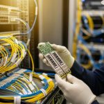
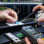
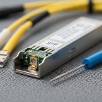
Before you compare OM3 vs OM4, lock the transceiver class you will deploy. Many multimode optics use LC connectors and operate at 850 nm, but the reach varies by data rate and by whether the optic is designed for OM3 or OM4. In practice, technicians measure end-to-end loss (including patch cords and splices) and then confirm that the module’s required optical power and receiver sensitivity can tolerate that budget.
Below is a quick comparison engineers use when mapping cabling to transceiver models. Note that exact reach depends on the specific optical standard (for example, SR variants) and the transceiver vendor’s characterization.
| Spec | OM3 Multimode | OM4 Multimode |
|---|---|---|
| Typical wavelength | 850 nm (common SR use) | 850 nm (common SR use) |
| Modal bandwidth (effective) | Designed for lower modal bandwidth than OM4 | Higher modal bandwidth than OM3 |
| Common “Ethernet SR” reach class | Often supports shorter reach at higher rates | Often supports longer reach at higher rates |
| Connector style | Typically LC (duplex) | Typically LC (duplex) |
| Temperature range (module-dependent) | Usually 0 to 70 C for standard, wider for industrial | Usually 0 to 70 C for standard, wider for industrial |
| Transceiver examples (field common) | Cisco SFP-10G-SR (varies by revision), Finisar FTLX8571D3BCL class optics | FS.com SFP-10GSR-85 class optics, many OM4-rated SR optics |
Image cleanliness matters: dirty endfaces can create excess insertion loss and back-reflections, which show up as receive signal degradation long before the link completely fails. Always treat patch-panel work as a fiber-optic “finish carpentry” task: inspect, clean, test, document.
Real deployment scenario: choosing OM3 vs OM4 in a 3-tier data center
Consider a 3-tier leaf-spine data center with 48-port 10G ToR switches in each rack row. You plan to run 10G SR uplinks from top-of-rack switches to aggregation, using multimode optics over patch panels. The estimated average horizontal run is 55 m including patch cords and a couple of consolidation splices. You budget for Cisco SFP-10G-SR-class transceivers in the near term, and you leave room for a future upgrade to 25G on selected pairs.
If the cabling plant is OM3, you may find that some links operate close to module reach margins once you include patch cords, aging connectors, and conservative loss assumptions. If the plant is OM4, you typically gain headroom for the same physical topology, which reduces the probability of “works in the lab, fails in production” behavior. In field acceptance, you validate with an OTDR or OLTS workflow and confirm that measured link loss stays comfortably below the optical budget for the specific transceiver SKU.
For the upgrade path, technicians often standardize on OM4 because it reduces the number of “special case” optics and keeps the optics bill-of-materials more consistent across racks. That consistency lowers operational risk: fewer module types to stock, fewer compatibility surprises during spares swaps, and faster troubleshooting.
Decision checklist: how engineers pick OM3 vs OM4 for transceiver selection
Use this ordered checklist during design review or during a field migration. It is optimized for teams that must pass acceptance testing and minimize rework.
- Define the target transceiver class and speed: example SR at 10G, or SR at 25G. Confirm the exact part number and its rated fiber type in the datasheet.
- Measure end-to-end distance and loss: include patch cords, jumpers, and splices. Use OLTS results with connector inspection; do not rely on cable reel “spec estimates.”
- Match fiber type to module rating: OM4-rated optics are usually compatible with OM3, but the inverse may fail at higher data rates or longer runs. Validate vendor guidance explicitly.
- Confirm connector type and cleanliness plan: ensure LC duplex polarity and cleaning steps are standardized. A correct fiber type cannot compensate for dirty optics.
- DOM support and monitoring needs: if your operations require Digital Optical Monitoring, confirm DOM availability for the exact module. Many vendors support DOM but not all SKUs expose every metric.
- Operating temperature and enclosure constraints: check module temperature range (standard vs extended) and airflow assumptions in each rack.
- Vendor lock-in risk and spares strategy: if you rely on one OEM’s reach assumptions, you may pay more for replacements later. Consider third-party optics with documented compatibility and consistent DOM behavior.
Pro Tip: In mixed patch panels, the biggest “hidden variable” is not the fiber type; it is the patch cord type and age. Field teams often standardize patch cords to a single vendor and connector polish style, then re-run OLTS after every batch of reconnections to prevent a few bad jumpers from turning into a rack-wide outage.
Common pitfalls and troubleshooting that actually save outages
Even when OM3 vs OM4 seems straightforward, real networks fail for predictable reasons. Use these failure modes as a rapid triage script.
Pitfall 1: Assuming OM3 and OM4 are interchangeable at the same reach
Root cause: Modal bandwidth differences affect higher-rate SR performance and can push links beyond receiver sensitivity margins when you include real-world patch cord loss. OM4 provides more bandwidth headroom, while OM3 may be marginal at longer runs.
Solution: Verify the exact transceiver part number reach table for OM3 and OM4. Then compare measured OLTS loss against the module’s optical budget. If you are near the edge, shorten the link or replace patch cords, not just the optics.
Pitfall 2: Cleanliness failures that mimic “wrong fiber type”
Root cause: Dust on connector endfaces increases insertion loss and causes unstable receiver levels. The symptom can look like a marginal OM3/OM4 issue because the link drops intermittently as power levels and temperatures shift.
Solution: Inspect every LC endface with a scope, clean with lint-free wipes and approved cleaning tools, and re-test. For persistent issues, check for connector damage or excessive polish defects and replace the patch cord.
Pitfall 3: Polarity and duplex mapping errors in patch panels
Root cause: Multimode duplex cabling can be reversed during patching, causing transmit to hit the wrong receive fiber path. Some optics may still establish link briefly, then fail under load or after reboots.
Solution: Confirm A-to-A and B-to-B mapping per your labeling scheme. Use a continuity check and then validate with link-up behavior and receive power readings (DOM if available).
Pitfall 4: DOM/EEPROM mismatch surprises during hot swaps
Root cause: Some third-party modules expose different DOM behavior or calibration scaling, and certain switches enforce strict optics compatibility. This can present as “module not recognized” rather than a fiber loss issue.
Solution: Keep a validated optics matrix for each switch model and firmware version. Test hot-swap behavior during staging, and verify DOM alarms in monitoring systems before moving to production.
Cost and ROI: choosing the cheaper optics without buying future rework
Typical pricing varies by region and volume, but real-world budgets often look like this: OEM multimode SR optics frequently cost in the hundreds of dollars per transceiver, while compatible third-party modules can be meaningfully lower. The bigger lever is total cost of ownership: if OM4 reduces the number of marginal links, you avoid truck rolls, emergency patch cord swaps, and the operational drag of holding multiple optics SKUs.
For TCO, account for:
- Installation labor: cleaning, inspection, and OLTS testing time
- Failure and rework rates: marginal links create repeat troubleshooting cycles
- Spare inventory: fewer module types means less warehouse complexity
- Upgrade flexibility: OM4 is often more forgiving for higher-rate SR migration
Practical ROI view: OM4 cabling can cost more at the time of installation, but it often pays back when you later standardize transceiver selection and reduce the number of “special case” runs that require shorter patching or different optics.
FAQ: OM3 vs OM4 fiber for multimode transceiver choices
Can I use OM4-rated transceivers on OM3 fiber?
Often yes, because OM4-rated optics are designed with higher modal bandwidth in mind. However, the safe answer is to confirm the specific transceiver datasheet reach table for OM3 and OM4. If you are near the edge of reach, validate with measured OLTS loss.
What is the fastest way to verify whether my link will work?
Run OLTS (end-to-end loss) and compare the result to the optical budget in the transceiver datasheet. Then clean and re-test after any connector work. If you have DOM, monitor receive power and error counters during link load.
Do I need different patch cords for OM3 vs OM4?
Patch cords must match connector type (usually LC duplex) and should be kept consistent in length and quality. Fiber type compatibility is important, but connector cleanliness and insertion loss dominate in practice. Avoid mixing unknown patch cord vendors without re-testing.
Will my switch accept third-party optics with DOM?
Some switches accept a wide range of optics, while others enforce strict compatibility rules by firmware and configuration. Validate against your switch model and software version, and test hot-swap behavior in staging. Keep a documented optics compatibility matrix to prevent surprises.
What temperature and aging effects should I consider?
Module temperature affects laser output and receiver stability, and connector aging can increase insertion loss over time. Plan for normal rack airflow, verify module temperature range, and re-run loss measurements during major maintenance cycles. If you see intermittent links, inspect connectors before replacing optics.
Is OM4 always the best choice for new installs?
Not always, but it is commonly the safest choice when you anticipate higher-rate SR upgrades or want extra link margin. If your distances are very short and your transceiver selection is fixed, OM3 can be cost-effective. Make the decision using measured loss and transceiver reach tables, not assumptions.
If you want a fast next step, map your current cabling distances to the exact SR transceiver SKUs you plan to deploy, then validate with OLTS and connector inspection. For a related topic, review Choosing multimode transceivers by speed and reach and build a repeatable acceptance checklist for every new optics batch.
Author bio: I have deployed multimode and single-mode optics in production data centers, validating reach with OLTS and debugging marginal links down to connector loss and receiver thresholds. I write field-first guidance for engineers who need reliable transceiver selection, not just spec-sheet promises.