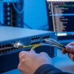
If your AI workloads are bottlenecked by storage or east-west traffic, you can often fix it by upscaling fiber links. This guide helps network engineers and data center operators evaluate cost versus throughput for AI networking, then execute a safe, standards-aligned upgrade with the right transceivers. You will also get practical troubleshooting steps for the most common optics and compatibility failures.
Prerequisites: what you must measure before buying optics
Before you change anything, confirm the limiting factor: congestion, link oversubscription, or inadequate optics reach. In a typical leaf-spine fabric, measure port utilization, retransmits, and latency under load using switch telemetry. For AI networking, also capture job-level traffic patterns during training and inference windows so you can size uplinks realistically.
Field-ready prerequisites:
- Traffic evidence: 95th percentile utilization, oversubscription ratio, and tail latency (p99) on switch egress.
- Distance map: fiber run lengths in meters, plus patch-cord loss budget and connector type.
- Switch compatibility: vendor SFP/QSFP optics support matrix and DOM behavior requirements.
- Operational constraints: maintenance window, spare optics inventory, and cooling limits around transceivers.
Update date: 2026-05-01. References reflect IEEE and vendor guidance listed below.
Step-by-step implementation: cost-benefit fiber upscaling for AI networking
This section is a numbered build plan you can run like a field project, from measurement to cutover.
Quantify the throughput gap with a simple sizing model
Start with your current link rate and required headroom. Example: if your AI cluster sees 2.4 Tbps aggregate east-west demand during training bursts but your leaf uplinks total only 1.6 Tbps, you have a sustained deficit. Convert that into the number of additional 10G/25G/40G/100G links required, then factor expected growth (often 20 to 40 percent over the next quarter).
Expected outcome: a target upgrade rate per leaf (for example, 25G per server port to 100G uplinks) with a clear justification tied to observed utilization.
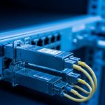
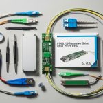
Select optics by reach, wavelength, and connector loss budget
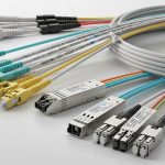
Upscaling fiber links is not only about higher bandwidth; it is also about ensuring the optical budget remains within receiver sensitivity and link loss. For short-reach AI networking inside data centers, SR modules (multimode fiber) or LR/ER (single-mode) are common, depending on distance and cabling.
Use IEEE-aligned expectations: Ethernet physical layers are defined in IEEE 802.3 for 10G/25G/40G/50G/100G families, while module behavior and management often follow vendor DOM implementations. For standards context, see Source: IEEE 802.3 Overview.
| Module example | Data rate | Wavelength | Typical reach | Fiber type | Connector | DOM / management | Operating temp |
|---|---|---|---|---|---|---|---|
| Cisco SFP-10G-SR | 10G | 850 nm (nom.) | ~300 m (MMF, spec-dependent) | OM3/OM4 multimode | LC | Supported on most Cisco platforms (verify) | ~0 to 70 C class (verify datasheet) |
| Finisar FTLX8571D3BCL | 10G | 850 nm (nom.) | ~400 m (MMF class spec-dependent) | OM4 multimode | LC | Usually supports DOM (verify) | Typical transceiver industrial/extended ranges vary |
| FS.com SFP-10GSR-85 | 10G | 850 nm (nom.) | ~400 m (MMF, spec-dependent) | OM4 multimode | LC | DOM varies by SKU | Varies by SKU; check datasheet |
| Common 25G/100G SR optics (varies by vendor) | 25G or 100G | ~850 nm | ~70 m to 400 m (depends on OM class and modulation) | OM3/OM4 multimode | LC (often) | DOM strongly recommended for troubleshooting | Verify transceiver class |
Expected outcome: a shortlist of optics that fit distance, connector type, and management requirements for AI networking.

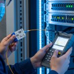
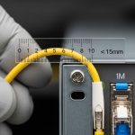
Run a loss budget and polarity check before the swap
For multimode, confirm you have enough link margin after patching. Include fiber attenuation, connector insertion loss, and aging considerations. Also verify polarity: MPO/MTP polarity adapters must match the transceiver and switch optics requirements, or you will see link flaps and low optical power.
Expected outcome: a passed loss budget and verified polarity plan that prevents avoidable optical bring-up failures.
Pilot in one pod, then cut over with controlled rollback
Deploy the upgrade in one leaf pod or one aisle first. Use a change window to swap optics and confirm link up, then validate traffic with a controlled test (for example, sustained iPerf3 flows or vendor traffic generator patterns). Keep old optics in labeled anti-static packaging for immediate rollback.
Expected outcome: validated link stability (no CRC spikes, no LOS/LOF events) before scaling.
Validate AI workload metrics, not just link counters
After cutover, correlate network metrics with training throughput: job completion time, GPU utilization stability, and p99 latency. This is where AI networking ROI becomes real, because link speed alone may not improve training if the bottleneck is elsewhere (storage, CPU preprocessing, or all-reduce configuration).
Expected outcome: measurable reduction in training bottlenecks and improved tail latency under real traffic.

Selection criteria checklist for upscaling fiber links
- Distance and fiber type: OM3/OM4 multimode versus single-mode, plus connector and patch-cord loss.
- Switch compatibility: vendor optics support list; verify that the exact transceiver model is validated.
- DOM support: confirm telemetry availability for Tx/Rx power and alarms to speed incident response.
- Operating temperature and airflow: ensure the planned optics class stays within rated range during peak cooling loads.
- Budget and TCO: compare OEM optics versus third-party, including failure rate risk and RMA logistics.
- Vendor lock-in risk: validate whether your platform enforces strict optics authentication or has compatibility quirks.
Pro Tip:
In field incidents, the fastest “root cause” is often not bandwidth at all, but optical budget drift from dirty connectors. Before concluding a module is incompatible, clean both ends with lint-free wipes and an optical fiber inspection scope, then compare Tx/Rx power versus baseline DOM readings. This frequently resolves intermittent link drops after an upgrade.
Common mistakes and troubleshooting tips
Failure mode 1: Link comes up then flaps during traffic
Root cause: excessive insertion loss, dirty connectors, or mismatched polarity on MPO/MTP links. Solution: inspect and clean, then re-check polarity adapters and patch-cord mapping; confirm DOM Tx/Rx power is within expected thresholds for the receiver.
Failure mode 2: Receiver reports low optical power or high error counters
Root cause: wrong optics SKU for the fiber plant (for example, SR module used beyond its OM class reach). Solution: validate your distance against the module’s rated reach for your OM3 or OM4, and update the loss budget including patch cords and splices.
Failure mode 3: Switch rejects third-party optics or disables the port
Root cause: optics authentication behavior, unsupported DOM implementation, or missing required EEPROM fields. Solution: use the vendor compatibility matrix; if you must use third-party, test in a pilot pod and retain OEM spares for rollback.
Cost and ROI note: what to expect in real deployments
Typical street pricing varies by rate and vendor, but for budgeting: OEM 10G SR optics often cost more than third-party equivalents, while 25G and 100G SR optics can be several times the per-port cost of 10G. A practical TCO model includes transceiver unit cost, expected failure/replace rate over the first 24 to 36 months, and labor for cleaning, inspection, and RMA handling.
ROI improves when the upgrade reduces job wait time or prevents oversubscription-induced tail latency. In many AI networking deployments, the biggest “hidden cost” is downtime during re-cabling; therefore, pilots, loss budgets, and DOM-based validation often pay for themselves quickly.