If your ToR switches keep flapping links or you are replacing optics under tight change windows, you need an engineering-grade SFP module comparison that goes beyond marketing tables. This article helps network and facilities teams choose between 10G SFP and QSFP optics using real compatibility constraints, measured operating limits, and field troubleshooting patterns.
Why SFP vs QSFP keeps breaking networks in real racks

In many data centers, the optics decision is treated like a commodity purchase, but the physical form factor drives electrical signaling, port mapping, and sometimes optics firmware behavior. SFP modules typically target 1G to 10G per lane-class systems, while QSFP modules often serve 25G to 100G class interfaces using different lane counts and higher aggregate bandwidth. IEEE 802.3 defines Ethernet physical layers (PHY) and link behaviors; however, switch vendors add their own firmware checks, DOM handling, and optics qualification lists.
The result is predictable: a module can be “electrically possible” yet fail due to DOM data mismatch, fiber polarity, laser safety class assumptions, or switch-side compatibility gating. For field teams, the fastest path is to compare optics by wavelength, reach, connector type, power budget, temperature range, and DOM support before swapping hardware.
What changes when you move from SFP to QSFP
At the signal level, QSFP-based systems commonly use multi-lane aggregation with higher per-module optical power handling and different serialization. At the operational level, QSFP ports are frequently mapped differently in switch configs (for example, breakout profiles), so a “same speed” assumption can be wrong. In practice, SFP modules are often used for 10G SR short reach, while QSFP is used for higher-speed uplinks or aggregation tiers.
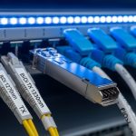
[[IMAGE:Close-up photography of a switched rack showing two adjacent rows of optics cages: one row labeled for SFP with small silver modules and another row for QSFP with larger black modules; shallow depth of field, 85mm lens look, cool warehouse lighting, realistic fiber patch cords with LC connectors visible.]
Key specs that matter in a true SFP module comparison
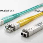
When you compare optics, you are comparing a full link budget: transmitter type, receiver sensitivity, chromatic dispersion tolerance, and connector cleanliness. For short-reach Ethernet, the most common reference points are 850 nm multimode (MMF) for SR and 1310/1550 nm single-mode (SMF) for LR/ER class optics. Even if the port speed is identical, a mismatched wavelength or reach category can cause marginal links that pass during initial testing but fail under temperature swings.
Practical comparison table: 10G SR SFP vs 10G QSFP-class
Below is a field-oriented comparison for commonly deployed configurations. Exact values vary by vendor and part number, so always verify against the specific datasheet and the switch optics compatibility list.
| Parameter | Typical 10G SFP SR | Typical 10G QSFP (10G-class) |
|---|---|---|
| Ethernet rate | 10GBASE-SR (10.3125 Gb/s) | 10GBASE-SR or vendor 10G-class QSFP profile |
| Wavelength | 850 nm | 850 nm in SR-style variants |
| Fiber type | OM3/OM4 MMF | OM3/OM4 MMF (profile-dependent) |
| Reach (typical) | 300 m on OM3, 400 m on OM4 | Often similar reach claims when implemented as 10G SR, but verify part number |
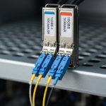
| Connector | LC (duplex) | LC (duplex) or vendor-specific cage wiring |
| DOM | Usually Digital Optical Monitoring supported (implementation varies) | Usually DOM supported; switch may require DOM compatibility |
| Operating temperature | Commonly 0 to 70 C (commercial) or -40 to 85 C (extended) | Same concept; verify module grade vs your room profile |
| Power class | Typically within SFP budget; verify vendor datasheet | QSFP power budget may differ due to form factor and thermal design |
| Switch compatibility | Often SFP-qualified list; some platforms are strict on third-party DOM | QSFP-qualified list can be stricter; breakout profiles can complicate mapping |
Where to anchor your decisions: IEEE and vendor qualification
IEEE 802.3 defines the physical layer behavior for Ethernet over fiber, but it does not guarantee that a switch will accept every vendor’s module. Your authoritative sources are the switch vendor optics compatibility matrix and the transceiver vendor datasheet for DOM fields, TX/RX optical characteristics, and temperature grade. For PHY expectations, see [Source: IEEE 802.3 Ethernet and physical layer specifications] and for vendor behavior, see [Source: Cisco SFP/QSFP transceiver compatibility guidance] and [Source: Juniper optics compatibility notes]. For optics examples, typical SR modules include Finisar FTLX8571D3BCL and Cisco-branded equivalents, and third-party options like FS.com SFP-10GSR-85 are common in cost-sensitive deployments.
Pro Tip: In most field failures that look like “bad optics,” the root cause is connector loss from dust or incorrect polarity rather than an outright module defect. Before replacing hardware, clean LC connectors and confirm RX/TX mapping with a light meter or continuity check, then re-run link diagnostics after a controlled warm reboot.
[[VIDEO:Handheld macro video walkthrough of an LC duplex fiber cleaning process: show a gloved technician using lint-free wipes and a fiber cleaning pen on two LC ferrules, then insert them into an SFP cage while the camera focuses on dust removal and connector alignment; end with a close-up of link LEDs stabilizing on a network switch interface.]
Deployment scenario: choosing optics in a 3-tier leaf-spine fabric
Consider a 3-tier data center with 48-port 10G ToR switches feeding a leaf-spine aggregation using two uplinks per server rack. Each ToR has 24 active 10G downlinks to servers and 4 active 10G uplinks to aggregation, totaling 28 optics per ToR when using SR over OM4. If you replace 60 ToRs during a maintenance window, that is 1,680 optics touched at once, so even a 0.5% failure rate becomes 8 to 10 modules that must be diagnosed fast.
In this environment, 10G SR SFP is typically chosen for downlinks because it matches the rate and reaches within typical OM4 spans (often 50 to 120 m patch-to-rack). QSFP is more likely used for higher-speed aggregation uplinks, or when the switch offers QSFP ports that reduce port count. If you try to force QSFP modules into a 10G SFP-style operational assumption, you can end up with port mapping issues and DOM gating, especially when breakout profiles are enabled on the chassis.
Selection criteria checklist for SFP module comparison
Use this ordered checklist when you are deciding between SFP and QSFP optics for the same logical link. It is designed for engineers who must pass change control with minimal downtime.
- Distance and fiber type: Confirm OM3/OM4/OS2 and measured link length (including patch cords). If you cannot measure, assume worst-case and derate.
- Optical reach category: Match SR/LR/ER expectations to wavelength class. Do not treat “850 nm” as interchangeable across all vendors.
- Switch compatibility: Verify the exact part number against the chassis optics matrix. Many platforms reject third-party DOM fields.
- DOM support and thresholds: Confirm DOM availability, sensor field mapping, and whether the switch expects specific alarm behavior.
- Operating temperature grade: Use extended temperature optics if your aisle hits 40 C and exhaust air is higher near dense cages.
- Budget and total cost of ownership: Compare OEM vs third-party pricing, expected failure rates, and warranty terms.
- Vendor lock-in risk: If you plan multi-vendor sourcing, test one batch in a staging switch and validate DOM and error counters.
Common pitfalls and troubleshooting: what fails first
Even with correct specs, optics swaps often fail due to operational details. The following are common mistakes with root cause and solution patterns that show up in field tickets.
Link up, but errors climb within minutes
Root cause: Marginal optical power from dirty connectors or fiber micro-bending; DOM may show weak RX without failing hard. Solution: Clean both ends of the LC duplex connectors using approved methods, re-seat modules firmly, and re-check link counters after a stable warm period. If available, run an optics diagnostic that reports received power and temperature.
Module is rejected or interface stays down
Root cause: Switch-side optics gating: DOM field mismatch, unsupported transceiver type, or breakout profile mismatch. Solution: Confirm the exact port mode (for example, whether QSFP is set for breakout). Cross-check the module part number against the vendor compatibility list, and ensure DOM is enabled if the platform requires it.
Wrong polarity or swapped duplex direction
Root cause: Duplex LC fibers are easy to flip; TX from one end must connect to RX on the other. Solution: Verify polarity using a polarity tester or label mapping, then re-terminate or swap patch cords. After correction, check for stable link negotiation and reduced CRC error rate.
Temperature-related intermittent failures
Root cause: Using commercial temperature modules in hot aisles; laser bias shifts and receiver sensitivity degrades. Solution: Replace with extended temperature modules, improve airflow near the cage, and monitor module temperature via DOM alarms.
Cost and ROI note: buying optics without surprises
Real pricing varies by volume and sourcing channel, but typical street ranges for 10G SR optics are often in the tens of dollars for third-party units and higher for OEM. In many enterprise deployments, OEM optics might cost roughly 1.5x to 3x third-party pricing, but OEM warranties and switch support processes can reduce downtime costs. For TCO, include labor for cleaning/validation, the cost of maintenance window time, and the expected probability of rework when a module is not accepted by the chassis.
If your failure budget is tight, run a staged validation: deploy a small pilot batch (for example, 10 to 20 modules per module type) across representative ports and validate link stability over 72 hours with temperature swings. That small test often prevents a multi-rack outage during mass replacement.
FAQ
What does SFP module comparison change for a 10G SR design?
It changes your selection discipline: you compare reach category, wavelength, DOM behavior, and switch acceptance. A correct spec sheet does not guarantee a switch will accept the module, especially with strict optics policies. Always verify the exact part number against the platform matrix.
Can I replace an SFP with a QSFP module at the same port speed?
Only if the switch hardware supports that form factor and the port mode matches the intended lane configuration. Many systems have different physical cages and different breakout settings for QSFP. Treat “same line rate” as insufficient without confirming the port mapping and optics type requirements.
How do I validate optics before a production rollout?
Use a staging switch that matches the production model and firmware, then test link stability while monitoring DOM temperature and receiver power. Validate that interface counters (CRC, FCS, and error states) remain stable under normal traffic. For fiber, clean and verify polarity first to avoid false negatives.
Are third-party SFP or QSFP modules safe for data center use?
They can be safe when they match the switch compatibility list and the module meets the required DOM expectations. The risk is not just optical performance; it is also acceptance logic, DOM field mapping, and warranty coverage. Buy from vendors with published datasheets and clear return policies.
What are the quickest troubleshooting steps for a dead link?
Confirm port mode, module seating, and DOM acceptance, then check fiber polarity and cleanliness. After that, re-seat and re-test while watching link state transitions and error counters. If you still see instability, measure received optical power if your platform reports it.
When should I choose extended temperature optics?
Choose extended temperature when your aisle and cabinet exhaust can exceed 40 C near dense cages or when you cannot control airflow during seasonal peaks. Also choose it if the modules will sit near high-heat components for extended periods. DOM alarms can help, but prevention via correct grade is better than reactive swaps.
For stable Ethernet links, a good SFP module comparison is really a compatibility and link-budget workflow: verify optics specs, confirm switch acceptance, and treat fiber cleanliness and polarity as first-class variables. Next, review fiber transceiver compatibility and DOM monitoring to tighten your validation process before the next maintenance window.
Author bio: I design and validate fiber optics deployments in live data centers, focusing on optics acceptance, DOM telemetry, and link stability under temperature swings.
Author bio: I also shoot practical documentation for field teams, translating cage layouts and connector mechanics into clear, repeatable change procedures.