You are standing in a wiring closet with a half-populated rack, and the switch ports insist on “optical module not present.” This article helps network engineers and field technicians choose between SR vs LR SFP+ when deploying 10GBase-SR and 10GBase-LR optics. You will learn the operational differences, how to validate compatibility, what to check in the optics before closing the panel, and how to troubleshoot the most common failures.
Why SR vs LR SFP+ feels confusing in the field
On paper, SR and LR both live in the SFP+ ecosystem and both target 10 Gigabit Ethernet. In practice, 10GBase-SR is built for short reach over multimode fiber, while 10GBase-LR is built for longer reach over single mode fiber. The confusion usually starts when someone labels patch cords loosely, mixes fiber types, or assumes “same data rate equals same optics.”
When I deploy these in real cabinets, the deciding factor is almost never the headline reach alone. It is the fiber plant already installed, the transceiver budget behavior under temperature, and whether the switch vendor enforces optic compatibility checks. IEEE defines the standards, but vendors implement guardrails in their SFP+ cages and optical diagnostics.
For authoritative baselines, use IEEE 802.3 for 10GBase-SR and 10GBase-LR specs, and vendor datasheets for DOM behavior and optical power limits. IEEE 802.3 standard home [Source: IEEE Standards]. For a practical optical reference, also consult transceiver vendor engineering notes and switch compatibility guides. Cisco support and compatibility [Source: Cisco Support].
10GBase-SR vs 10GBase-LR: the specs that actually drive decisions
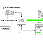
Let us translate the standards into the values you can measure or verify quickly during a site visit. The key differences are wavelengths, fiber type, typical reach, and how the optics behave with DOM (Digital Optical Monitoring) and link training.
| Spec | 10GBase-SR SFP+ | 10GBase-LR SFP+ |
|---|---|---|
| Ethernet standard | 10GBase-SR | 10GBase-LR |
| Wavelength | ~850 nm | ~1310 nm |
| Fiber type | OM3 or OM4 multimode (commonly) | Single mode fiber (OS2) |
| Typical reach (cable plant) | Up to 300 m (OM3), up to 400 m (OM4) | Up to 10 km (OS2) |
| Connector style | Usually LC | Usually LC |
| Data rate | 10.3125 Gb/s (10G Ethernet) | 10.3125 Gb/s (10G Ethernet) |
| DOM support | Commonly supported (check vendor) | Commonly supported (check vendor) |
| Operating temperature | Often 0 to 70 C for standard; some offer extended | Often 0 to 70 C for standard; some offer extended |
In my own deployments, I treat these specs as a “fit test.” If your patch panel ends in OM3/OM4 multimode, SR is the right physics. If the fiber is OS2 single mode, LR is the right physics. Trying to force SR onto single mode can appear to “work” briefly in a lab, but real plants suffer from budget mismatch, modal behavior differences, and vendor compatibility checks.

Reach, budget, and fiber plant: how to choose SR vs LR without guessing
Selection is less about maximum reach and more about whether your link margin survives real attenuation, connector loss, and aging. IEEE defines link performance under reference conditions, but you still have to account for patch cord length, number of mated connectors, and splice quality.
Use the fiber type and wavelength first
Start with the fiber designation on the cabling records and the patch panel labels. OM3/OM4 multimode aligns with 850 nm SR. OS2 single mode aligns with 1310 nm LR. If documentation is missing, you can sometimes infer fiber type by connector style and cable jacket markings, but the most reliable approach is to inspect the cable labeling and run an OTDR verification when allowed by your change window.
Then validate switch compatibility and DOM behavior
Many enterprise and carrier switches read the transceiver EEPROM and require certain identifiers before they enable the optical interface. In practice, you will see differences between OEM optics and third-party optics, even when both claim SFP+ 10GBase compliance. I have used Cisco SFP-10G-SR/SFP-10G-LR compatible optics successfully, but I always check the switch vendor compatibility matrix because the “link up” moment is where surprises show up.
For examples of commonly referenced components, you might see OEM-style part numbers like Cisco SFP-10G-SR and Cisco SFP-10G-LR, or optics from reputable vendors such as Finisar and FS. Example third-party models include Finisar FTLX8571D3BCL for 10GBase-SR and FS.com SFP-10GSR-85 for SR at 850 nm, though exact reach and DOM features depend on the specific SKU and temperature grade. Always confirm the exact datasheet for the module you intend to install.
Pro Tip: In field audits, I treat “DOM present” as a separate requirement from “link comes up.” Some optics will negotiate and pass traffic but report inaccurate diagnostics, which can mask a dying laser or a dirty connector until your BER rises. If your platform supports thresholds, set alerts for Rx power and temperature early, not after an incident.
Deployment scenario: choosing SR vs LR in a 3-tier data center
Consider a 3-tier leaf-spine topology with 48-port 10G ToR switches connecting to a spine via 10G uplinks. The leaf-to-ToR patching is short: 60 to 120 m of OM4 cabling in a cabling zone, with two LC connectors per link and no splices. For these uplinks, I typically specify 10GBase-SR SFP+ modules because OM4 supports the needed reach with comfortable margin, and the multimode optics are usually cheaper per port.
Now add a second environment: a regional aggregation closet where rack A must connect to rack B across a maintenance corridor with 3.5 to 7 km of routed fiber. That plant is OS2 single mode, and the physical separation makes SR unrealistic even if someone believes “we have plenty of link budget.” Here, 10GBase-LR SFP+ is the correct choice because it is designed for single mode at ~1310 nm and supports the longer reach needed.
During commissioning, I verify that each transceiver matches the expected fiber type and that the switch reports DOM values within the vendor’s stated ranges. If a module is swapped into the wrong optics cage during a patch-day rush, the interface may refuse to initialize or may show unstable link behavior. The fastest mitigation is usually a fiber-side correction plus module replacement, not repeated reseating.

Selection checklist: ordered factors engineers weigh
When I am helping a team standardize optics across sites, I use a repeatable checklist. It prevents the classic “we bought the wrong box” problem that costs weekends.
- Distance and reach class: compare your measured cable length plus patch cord overhead against SR and LR expected reach for your fiber type.
- Fiber type confirmation: OM3/OM4 for SR, OS2 for LR; verify with records or OTDR if documentation is questionable.
- Switch compatibility: check the switch vendor’s optics compatibility list for the exact transceiver model and temperature grade.
- DOM support and thresholds: confirm whether your platform reads DOM and what alarms it can trigger (Rx power, Tx bias, temperature).
- Operating temperature and airflow: ensure the module’s spec matches the enclosure environment; heat can shift optical power and increase error rates.
- Budget and TCO: compare OEM vs third-party pricing, but include failure rates, warranty terms, and the cost of downtime during replacements.
- Vendor lock-in risk: if your operations team prefers one vendor’s diagnostic behavior, standardize on that ecosystem to reduce troubleshooting variance.
Common pitfalls and troubleshooting tips that save hours
Optics issues often look like “bad transceiver,” but the root cause is frequently fiber hygiene, wrong module class, or connector loss. Here are the mistakes I see most in real rollouts.
Wrong fiber type installed under the same connector style
Root cause: SR optics at ~850 nm placed into a link expecting single mode OS2, or LR optics placed into multimode. Even if the connector fits, the optical path and launch conditions do not match the standard assumptions.
Solution: verify fiber type from labeling or OTDR. Replace the transceiver with the correct standard: 10GBase-SR for OM3/OM4, 10GBase-LR for OS2. Re-clean LC ferrules if you had to re-seat multiple times.
Dirty LC connectors causing intermittent link up and rising errors
Root cause: finger oils, dust, and micro-scratches on LC ferrules. This can produce a link that sometimes comes up, then flaps under temperature swings.
Solution: clean using approved fiber cleaning tools (dry wipe and inspection recommended). If available, inspect with a fiber microscope and re-clean until contamination is removed. After cleaning, re-check DOM Rx power and link error counters.
Incompatible third-party modules passing basic checks but failing diagnostics
Root cause: the transceiver may “work” but report unexpected DOM values or violate the platform’s threshold assumptions, leading to disabled ports or late instability.
Solution: start with a short pilot using a small batch at the same temperature and airflow conditions. Confirm that the switch accepts the module and that DOM thresholds behave as expected. Prefer modules with clear datasheets matching your switch generation.
Exceeding link budget with too many patch cords and connectors
Root cause: engineering drawings omit connector counts, or a patch cord was replaced with a longer one during a late-stage change. Each additional mated LC connector adds insertion loss and can push the link over the margin.
Solution: recalculate link budget using your fiber plant’s attenuation and connector/splice estimates. Reduce patch cord count, shorten runs, or move from SR to LR only when fiber type supports it and the switch supports it.

Cost and ROI: what SR vs LR costs over time
Price swings by brand, warranty, and temperature grade, but typical street ranges for 10G optics are often roughly: SR SFP+ modules in the lower to mid range per port, and LR SFP+ modules in a higher band due to single mode optics and reach performance. OEM modules can cost more but sometimes reduce compatibility friction. Third-party modules can be cost-effective, but the ROI depends on your operational maturity: if your team can validate DOM and thresholds quickly, third-party often pays off.
In total cost of ownership, include downtime risk. A wrong module across a large rollout can create outage windows large enough to erase the savings per transceiver. Also factor warranty terms and expected failure rates: optics are durable, but connector contamination and handling mistakes are the real enemy.
Operationally, SR optics can reduce total cabling cost when your environment already has OM4 installed and links stay within reach. LR optics can reduce the need for expensive fiber re-cabling when you already have OS2, avoiding long renovation cycles.
FAQ: SR vs LR SFP+ for 10GBase-SR and 10GBase-LR
Q1: Can I use LR SFP+ on multimode fiber just because the interface is 10G?
It is usually not a reliable or standards-aligned substitution. LR is designed around single mode behavior at ~1310 nm, while multimode SR is designed around ~850 nm modal performance. If you try it, you may see link failures or unstable performance that is hard to troubleshoot.
Q2: What is the practical reach difference between SR and LR SFP+?
SR is typically up to 300 m on OM3 and up to 400 m on OM4. LR is typically up to 10 km on OS2 single mode, assuming you meet link budget requirements. Real reach depends on connector counts, patch cord quality, and optical power margins.
Q3: Do SR vs LR SFP+ modules both support DOM?
Many modern SFP+ modules include DOM, but support varies by vendor and switch platform. Verify DOM compatibility with your switch model and the exact transceiver SKU, then confirm alarms for Rx power and temperature behave correctly during commissioning.
Q4: Why does my switch show “module not supported” even when the transceiver is brand-new?
Common causes include a mismatch in vendor compatibility, incorrect transceiver standard, or a temperature grade outside what the platform expects. Check the switch’s optics compatibility list and confirm the module’s wavelength and fiber type match the intended link.
Q5: What is the fastest way to troubleshoot a link that flaps after optics installation?
Start with fiber cleaning and inspection, then verify the fiber type and link budget. If the interface is accepted but errors rise, check DOM Rx power trends and compare them to the module datasheet. Re-seat carefully and avoid repeated insertions without cleaning.
Q6: Should I standardize on OEM optics or third-party optics?
If you need predictable compatibility and consistent DOM behavior, OEM optics can reduce friction. Third-party optics can be a strong ROI choice when you validate them in a pilot and have a process for DOM threshold monitoring and optical hygiene.
If you want a broader view of optics formats and how they affect density and upgrade paths, read QSFP+ vs SFP+ optics. Next, map your actual fiber plant to SR or LR standards and confirm switch compatibility before you order in bulk.
Author bio: I have spent years deploying and troubleshooting SFP+ optics in live data centers, from patch-day rollouts to OTDR-informed remediation. I write from the bench and the rack, focusing on measurable link margins, optics diagnostics, and post-install validation.