Choosing the right optics is a common source of late-night outages in modern server and storage networks. This quick reference compares 25GBASE SFP28 transceiver types for SR, LR, and ER, focusing on what field engineers verify: wavelength, reach, power, connector type, and operational limits. You will also get a distance-to-budget decision checklist plus troubleshooting patterns seen in the field.
SR, LR, and ER in 25G SFP28: what actually changes

Think of SR, LR, and ER as three “coaches” for the same trip distance, each with a different gear ratio. The “gear ratio” is the optical budget and transmitter/receiver design: SR is optimized for short reaches over multimode fiber, while LR and ER are optimized for longer reaches over single-mode fiber. In practice, your switch ports still expect a 25Gbps SFP28 electrical interface, but the fiber plant and link budget determine whether the link comes up cleanly and stays within spec.
At a standards level, these are defined by IEEE 802.3 for 25GBASE Ethernet optics, and vendors implement them with specific transceiver modules and optics front-ends. For baseline behavior, consult the IEEE 802.3 clause that covers 25GBASE optical interfaces and the transceiver datasheet for exact parameters like OMA, receiver sensitivity, and DOM availability. For vendor confirmation, cross-check the module model number against your switch vendor’s optics compatibility list. Source: IEEE 802.3 standards portal
Quick mapping: fiber type and typical reach
In most deployments, SR modules pair with OM3 or OM4 multimode fiber and target shorter runs, while LR and ER pair with OS2 single-mode fiber for longer runs. Typical reach targets you will see on datasheets are in the neighborhood of 100m for SR (depending on OM3 vs OM4 and vendor implementation), 10km for LR, and 40km for ER on 25GBASE-SR/LR/ER profiles. Always treat “reach” as a link-budget target, not a guarantee—patch cord loss, splice count, and connector cleanliness shift the margin.
Pro Tip: In the field, “works on the bench” can still fail after installation because fiber end-face cleanliness and patch cord composition change the effective optical power by several tenths of a dB. Before you blame the transceiver, verify polarity, clean connectors, and measure link margin with an OTDR or certified loss test results for the exact installed fiber path.
Side-by-side specs: 25GBASE-SR vs 25GBASE-LR vs 25GBASE-ER
Use the table below as your first pass when you are assigning optics to a link. Then validate the exact module part number against your switch model and the vendor’s DOM and temperature ratings. If you are running mixed optics across a leaf-spine fabric, standardize where possible to simplify spares and troubleshooting.
| Parameter | 25GBASE-SR (SFP28) | 25GBASE-LR (SFP28) | 25GBASE-ER (SFP28) |
|---|---|---|---|
| Typical wavelength | ~850 nm (multimode) | ~1310 nm (single-mode) | ~1550 nm (single-mode) |
| Target reach | ~100 m (OM3/OM4 dependent) | ~10 km | ~40 km |
| Fiber type | OM3/OM4 multimode | OS2 single-mode | OS2 single-mode |
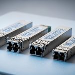
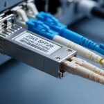
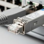
| Connector style (common) | LC (duplex) | LC (duplex) | LC (duplex) |
| Data rate / lane | 25.78125 Gbps (per IEEE 802.3 25GBASE) | 25.78125 Gbps | 25.78125 Gbps |
| DOM support (typical) | Yes (vendor-dependent) | Yes (vendor-dependent) | Yes (vendor-dependent) |
| Operating temp range (typical) | Commercial or extended (confirm datasheet) | Commercial or extended (confirm datasheet) | Commercial or extended (confirm datasheet) |
| Power class (typical) | Lower than long-haul in many designs; confirm datasheet | Moderate; confirm datasheet | Often higher than LR; confirm datasheet |
Concrete examples you may encounter in the field include Cisco-branded and third-party optics such as Cisco SFP-25G-SR-class modules for SR, and 25GBASE-LR/ER SFP28 modules with matching wavelength behavior. Third-party vendors also publish specific part numbers; for instance, Finisar/II-VI-style families like FTLX8571D3BCL appear in optical catalogs for 10G/25G variants depending on exact SKU, and FS.com and other suppliers offer SFP28 LR/ER modules with explicit reach and DOM specs. Always verify the exact SKU and whether it is truly SFP28 for 25GBASE operation, not a similarly named QSFP28 or older speed grade. Source: IEEE 802.3 working group resources
Distance, budget, and compatibility: how to choose the right type
Engineers rarely pick SR vs LR vs ER by reach alone. The real decision blends installed fiber quality, optics cost, switch compatibility, and how much operational risk your change window can tolerate. If you are building a new rack-to-rack design, it is usually cheaper to run multimode for short distances; if you are extending across buildings or long corridors, single-mode with LR or ER is often the only stable path.
Decision checklist (ordered like a field workflow)
- Distance and fiber type: Confirm the run length and whether the installed plant is OM3/OM4 or OS2. Do not assume—read the fiber designation on the building records.
- Switch and port compatibility: Check the switch vendor’s optics compatibility list for your exact switch model and firmware. Some platforms are strict about DOM behavior and supported transceiver vendors.
- Optical budget reality: Use certified attenuation results and connector/splice loss counts to validate margin. If you cannot get a measurement, treat the “max reach” as optimistic.
- DOM and monitoring needs: Decide whether you require temperature, bias current, transmit power, and receive power reporting. Verify that your network OS can read the DOM fields.
- Operating temperature: Choose modules rated for your environment. In hot aisles, extended temperature parts can be the difference between intermittent errors and stable links.
- Vendor lock-in risk: Weigh OEM optics versus third-party. OEMs may reduce compatibility surprises, while third-party can cut upfront cost if it matches DOM expectations.
- Spare strategy: For LR/ER, keep spares by type. Mixing SR and LR in a spare bin is a common root cause of “mystery outage” during RMA swaps.
Real-world deployment scenario: leaf-spine with mixed optics
In a 3-tier data center leaf-spine topology with 48-port 25G ToR switches, a common pattern is SR optics for rack-to-rack and LR/ER optics for longer spine uplinks. Suppose the leaf-to-spine distance is 120 m of OM3 multimode in one pod, but 4 km of OS2 single-mode across another building. The design team uses SR only where the certified plant supports it, and selects LR for the 4 km links; ER is reserved for cases where the certified loss budget plus splices pushes beyond LR’s margin.
Operationally, you will see link bring-up issues when the wrong fiber type is patched: SR modules expect multimode behavior, while LR/ER expect single-mode. During rollout, field engineers typically stage optics in labeled bags, verify DOM readings after insertion, and confirm link error counters (for example, FEC-related counters where applicable) remain stable after burn-in. This is also where cleaning and polarity checks prevent a large share of initial failures.
Common mistakes and troubleshooting that saves hours
When 25G links fail, the fastest fix is to avoid the top repeatable mistakes. Below are common failure modes seen during installs, along with likely root causes and practical solutions.
Wrong fiber type patched (SR vs LR/ER mismatch)
Root cause: SR is connected to an OS2 path (single-mode) or LR/ER is connected to an OM3/OM4 path (multimode). The link may not come up or may flap due to insufficient optical coupling.
Solution: Confirm fiber type labels in the tray, verify connector type, and trace the patch panel path. Re-terminate or repatch with the correct optics and fiber segment, then re-check link status and DOM receive power.
Dirty LC end-faces causing low optical power
Root cause: Connector contamination can introduce several dB of loss, which collapses margin—especially for LR/ER long-haul links.
Solution: Use a fiber inspection scope, clean with approved methods, and re-test with a certified loss meter. After cleaning, watch receive power trend in DOM for stability over several minutes.
Exceeding link budget with unaccounted patch cords/splices
Root cause: The “distance” in the drawing ignores additional patch cord length, extra connectors, or splices added during construction.
Solution: Pull certified test results for the exact installed route. If you must estimate, add conservative allowances for connectors and splices, then reduce effective reach by that margin.
DOM incompatibility or unsupported vendor optics behavior
Root cause: Some network OS versions expect specific DOM data formats or threshold behavior; third-party optics may report fields differently.
Solution: Confirm compatibility via the switch vendor’s list or test in a staging environment. If DOM monitoring is required for alerting, validate that alarms like TX/RX power out-of-range behave as expected.
Cost and ROI: OEM vs third-party optics in TCO terms
Typical street pricing for 25G SFP28 optics varies by reach and vendor. As a rough planning range, SR modules are often the lowest cost per port, while LR and ER modules cost more due to optical complexity and yield. In many environments, OEM optics carry a premium that can be justified when compatibility issues would otherwise drive labor hours, escalations, and extended downtime.
For TCO, include labor for installation, spare stocking, and failure rate over your warranty horizon. Long-haul modules (LR/ER) benefit most from careful selection because a small margin error can cause intermittent performance and repeated truck rolls. Third-party optics can be cost-effective, but only when your switch compatibility and DOM behavior are validated for your specific platform and firmware. Source: ANSI standards overview
FAQ
What are the main differences between 25GBASE SFP28 transceiver types SR, LR, and ER?
The biggest differences are fiber type and reach: SR targets short runs over OM3/OM4 multimode, while LR and ER target longer runs over OS2 single-mode. Wavelength differs too (SR is near 850 nm; LR near 1310 nm; ER near 1550 nm). Always confirm the exact reach and optical budget in the module datasheet.
Can I use an SR module for a single-mode link if the distance is short?
You should not rely on that. Even if the distance seems short, the optical design is optimized for multimode behavior; SR can fail to establish a stable link or can show high error rates. Use the module type that matches the fiber plant and the standards profile.
How do I verify DOM works with my switch for 25GBASE SFP28?
After insertion, check link-up status and read DOM fields such as transmit power and receive power on the switch CLI or telemetry interface. If your platform supports thresholds, confirm alarms trigger correctly by observing counters during a controlled change (for example, swapping a known-good optic). If DOM is critical for monitoring, validate in a staging environment first.
Why do LR or ER links flap after deployment even though they “should work”?
Common causes include connector contamination, patch panel polarity errors, or optical budget overruns from unplanned patch cord and splice loss. Another cause is environmental temperature swings that push marginal optics out of their operational window. Verify with an optical power measurement and fiber inspection before replacing modules.
Are third-party 25GBASE SFP28 transceivers safe to deploy?
They can be, but you must validate compatibility with your switch model and firmware, including DOM behavior if monitoring is required. Use a pilot deployment, keep OEM optics as a fallback for high-risk links, and document which exact part numbers passed your tests. Avoid mixing optics types in spares without clear labeling.
What should I log during a link bring-up for SR vs LR vs ER?
Log link status, DOM transmit and receive power, and any interface error counters. For LR/ER, also confirm that the measured receive power stays within the module’s recommended operating range over time. If you have telemetry, capture trends for at least several minutes after stabilization.
If you want fewer outages, treat optics selection like a checklist: match fiber type, validate link budget with installed measurements, and confirm DOM and temperature ratings on your exact switch platform. Next, review fiber transceiver compatibility checklist to standardize swaps, spares, and acceptance testing.
Author bio: Field-focused network writer who has supported 25G and 100G optical rollouts across leaf-spine and enterprise campus designs.
Author bio: Former deployment engineer who troubleshoots DOM telemetry, optical power margins, and physical-layer faults in live data centers.