Choosing the right SFP (Small Form-factor Pluggable) transceiver for Omron and Keyence controllers is less about “compatibility” in the abstract and more about matching electrical, optical, and network-layer requirements to the exact controller family and communication topology. In industrial automation, a correct SFP selection can reduce downtime, stabilize link quality, and simplify maintenance—while a mismatch can lead to intermittent link drops, negotiated speeds that don’t meet your throughput needs, or firmware/configuration conflicts. This guide explains what matters when selecting SFPs for Omron and Keyence controllers, how to verify compatibility safely, and how to design a reliable fiber link that works from day one.
What an SFP Does in Omron and Keyence Fiber Setups
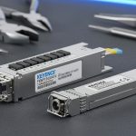
An SFP is a hot-pluggable optical/electrical transceiver that converts signals between the controller’s network interface and the fiber-optic cabling. In industrial environments, fiber links are often chosen to avoid EMI issues, extend reach, and improve reliability versus copper Ethernet. For controllers from Omron and Keyence, SFPs are commonly used with dedicated media converters or directly in controller/communication modules that support SFP-style optics.
At a high level, you must ensure three layers align:
- Physical layer: correct fiber type (single-mode vs multi-mode), wavelength (e.g., 1310 nm vs 1550 nm), connector type (LC/SC), and transmit/receive direction.
- Link layer: supported Ethernet speed (commonly 100BASE-FX, 1000BASE-SX/LX) and duplex behavior.
- System layer: controller/network configuration (IP/subnet, VLAN if used, managed switch behavior, and any vendor-specific settings).
Understanding Controller-Specific Constraints
Omron and Keyence controllers may both use fiber networking, but the supported transceiver types and module ecosystems can differ. The key is to treat the “SFP” label as a mechanical and electrical form factor—not a guarantee that every SFP will work. Controllers may require:
- Specific optics classes (for example, 1000BASE-LX for long reach single-mode).
- Specific vendor-certified modules for stable operation.
- Specific link initialization behavior (some devices expect certain auto-negotiation patterns, or they may not support auto-negotiation at certain speeds).
In practice, the safest approach is to align with the controller manufacturer’s supported SFP list or supported media list for the exact model and interface.
SFP for Omron Controllers: What to Verify
For Omron, SFP usage typically depends on the model of the communication interface or fiber-capable network module you are installing. Omron ecosystems often include Ethernet-capable modules and fiber media adapters that use standard optics. However, the controller’s NIC and the module’s firmware still determine which transceiver parameters are accepted.
1) Confirm the Omron model and port type
Start with the exact Omron controller/IO/network module model number. Then confirm whether the port is:
- Direct SFP cage (true SFP insertion), or
- Media conversion (SFP used in a dedicated fiber module or switch), or
- Specialized fiber interface that may accept only certain optics.
This distinction matters because some Omron modules present different electrical expectations even if the form factor is “SFP-like.”
2) Match fiber type and wavelength
Typical combinations include:
- Multi-mode (MMF) with shorter reach optics (often 850 nm for Ethernet over MMF).
- Single-mode (SMF) with longer reach optics (commonly 1310 nm or 1550 nm).
Mixing MMF and SMF, or using the wrong wavelength band, can prevent link establishment or reduce optical margin to an unacceptable level.
3) Validate link speed expectations
Before deployment, verify the expected Ethernet speed for your topology. If your design requires gigabit throughput, choose SFPs rated for 1000BASE rather than 100BASE. Otherwise, the link may fall back to a lower speed, impacting PLC scan-time budgets for heavy traffic (e.g., bulk data transfers, machine vision streaming).
4) Use the correct connector and polarity (TX/RX)
Most industrial fiber troubleshooting failures come from physical mistakes:
- Wrong connector type (LC vs SC)
- Wrong polarity (reversed transmit/receive)
- Incorrect patch lead type
Even when the SFP optics are correct, reversed fiber can lead to “no link” or unstable link status.
SFP for Keyence Controllers: What to Verify
Keyence controllers and networking components also use fiber for robust industrial communication. Similar principles apply: ensure the SFP matches what the Keyence controller interface supports, including optics type, speed class, and the fiber link budget requirements.
1) Identify the Keyence interface family
Keyence offers a range of controllers and communications modules. Some systems support standard Ethernet optics through supported transceiver categories, while others rely on Keyence-specific module ecosystems. Your first step is to locate the Keyence documentation for the exact controller model and confirm:
- Which SFP types are supported
- Which Ethernet speed is supported on that port
- Any restrictions on third-party optics
2) Align SFP optics to the planned fiber infrastructure
If your facility already has a fiber plant installed, match the SFP wavelength and fiber type to that infrastructure rather than trying to “force” a different reach class. This is especially important in retrofits where patch panels and fiber runs are fixed.
3) Consider link management and switch behavior
Industrial networks frequently include managed or industrial-grade switches. Ensure the switch configuration aligns with the controller’s expectations:
- Auto-negotiation settings (on/off)
- Speed/duplex forced vs negotiated
- VLAN tagging consistency
- Link monitoring and port security features
When a switch expects a certain negotiation behavior and the controller behaves differently (common with some industrial optics), you can see intermittent connectivity.
Where the “Keyence fiber module” Fits In
In many real installations, the term Keyence fiber module refers to Keyence’s dedicated fiber-capable communication module or transceiver-bearing component within the Keyence ecosystem. The practical point for installers is that the SFP you choose often must match the requirements of that specific module, not just the general fiber category.
Think of the “Keyence fiber module” as a system boundary. The SFP’s optics must be compatible with:
- The module’s supported optical wavelengths
- The module’s expected link speed
- The module’s diagnostics and link state reporting
If you are selecting SFPs for a Keyence setup that uses a Keyence fiber module, the safest path is to follow Keyence’s supported transceiver list for the exact module model, then verify the fiber plant matches the required reach class.
Choosing the Right SFP: A Practical Compatibility Checklist
To avoid costly trial-and-error, use this checklist before you purchase or deploy any SFP for Omron and Keyence controllers.
Step 1: Determine the required Ethernet speed
- Need 100 Mbps only? Choose 100BASE-FX compatible optics.
- Need gigabit performance? Choose 1000BASE-SX/LX compatible optics depending on fiber type and distance.
Step 2: Determine fiber type and distance
- Multi-mode: typically shorter reach; verify the installed cable class if you’re near the limit.
- Single-mode: longer reach; verify wavelength (1310/1550) aligns with optics and plant.
Step 3: Match connector type and polarity
- Confirm LC vs SC (and any adapter requirements).
- Confirm TX/RX pairing rules for your patch panels.
Step 4: Confirm the controller’s supported optics list
- Use Omron and Keyence documentation for the exact controller/module model.
- If you must use third-party optics, verify they are explicitly supported (or certified) for that controller/interface.
Step 5: Verify switch and network configuration
- Match speed/duplex negotiation strategy.
- Verify VLAN tagging and QoS policies if used.
- Check for link monitoring thresholds that may treat marginal optical links as faults.
Common Failure Modes (and How to Prevent Them)
Most SFP problems in industrial networks are predictable once you understand the root causes. Below are frequent failure modes when integrating SFPs with Omron and Keyence controllers.
No link / link flaps
- Cause: wrong wavelength or fiber type (MMF vs SMF).
- Cause: TX/RX polarity reversed.
- Cause: optical budget too tight (dirty connectors, high attenuation).
Prevention: clean fiber ends, verify polarity, use an optical power meter/OTDR or at least verify link margin with certified testing where possible.
Lower-than-expected throughput
- Cause: using 100BASE optics where gigabit is required.
- Cause: forced speed/duplex mismatch between switch and controller.
Prevention: confirm both endpoints support the negotiated speed and are configured consistently.
Intermittent communication during vibration or maintenance
- Cause: loose fiber patch connections, poor strain relief, damaged connectors.
Prevention: use proper cable management, label patch leads, and verify connector seating and strain relief.
Works in the lab, fails in the field
- Cause: facility fiber attenuation differs from expectations.
- Cause: temperature and environmental factors impact marginal optical links.
Prevention: validate with realistic cable runs and ensure optical margin is sufficient for worst-case conditions.
Design Patterns for Omron and Keyence Fiber Networks
To make SFP selection easier and more reliable, consider common network patterns used in industrial deployments.
Pattern A: Controller-to-Switch Fiber with Managed Switch
- Omron controller connected to an industrial switch via fiber SFP
- Keyence controller connected similarly
- Managed switch handles VLANs and monitoring
Best practice: keep speed/duplex configuration consistent across ports and avoid unnecessary forced settings unless required.
Pattern B: Redundant Links (where supported)
- Two fiber paths from controller to different switch ports
- Failover strategy depends on controller/network support
Best practice: standardize on identical SFP types and optics parameters for each path to reduce variability during failover.
Pattern C: Use of Media Converters for Isolation
- In some cases, you may isolate fiber segments using media converters
- SFP is installed in the converter or in a dedicated fiber interface module
Best practice: confirm both sides (controller interface and converter) negotiate the same speed and duplex and that the converter’s SFP mode matches the fiber type.
Verification and Testing Before Commissioning
Commissioning is where good engineering prevents production issues. A disciplined verification process should include both network-layer and physical-layer checks.
Physical verification
- Inspect and clean all fiber connectors
- Confirm correct patch lead polarity (TX to RX)
- Verify connector seating and strain relief
Optical verification
- Measure optical power (Tx/Rx levels) if equipment is available
- Confirm link margin is within the transceiver and plant expectations
- If you have access, perform OTDR checks for high-attenuation segments
Network verification
- Confirm link is up and stable for extended periods (not just on initial power-up)
- Validate IP addressing, routing, and any VLAN tagging
- Test application traffic patterns that reflect real machine workloads
Recommendations: How to Select SFPs for Omron and Keyence Together
When you integrate both Omron and Keyence controllers in the same industrial network, you want uniformity where possible. That reduces operational complexity during maintenance and troubleshooting.
- Standardize on a single fiber type and speed class across the plant segment (e.g., all gigabit over single-mode if that matches your reach).
- Use the supported transceiver list for each controller/module model, especially if the interface is associated with a Keyence fiber module or a specific Omron fiber interface.
- Keep optics parameters identical across endpoints (wavelength and reach class) unless you intentionally design for different segments.
- Plan spare transceivers with the exact same part numbers so you can swap quickly if a link fails.
Example Selection Matrix (Conceptual)
The table below is a conceptual example to help you map your requirements to the typical SFP categories. Always confirm exact supported models in Omron and Keyence documentation.
| Requirement | Typical Fiber Type | Common SFP Category | Notes |
|---|---|---|---|
| Short reach, gigabit | Multi-mode (MMF) | 1000BASE-SX | Verify MMF capability and distance to avoid marginal links |
| Long reach, gigabit | Single-mode (SMF) | 1000BASE-LX | Match wavelength band to controller/module support and plant optics |
| Legacy 100 Mbps | Multi-mode or single-mode | 100BASE-FX | Often used in smaller or legacy segments; check throughput needs |
Procurement and Maintenance Best Practices
Once your SFPs are selected and the network is live, the operational goal is repeatability. Maintenance teams should be able to replace a transceiver without re-deriving the entire compatibility logic.
Document the exact transceiver part numbers
Record the manufacturer, exact part number, wavelength, reach class, and connector type. If your deployment involves the Keyence fiber module, include the Keyence module model and port designation in your records.
Label patch cords and transceivers
- Label by endpoint (e.g., “KEYENCE PLC Port 1 → Switch A Port 12”)
- Keep a consistent polarity standard across the panel
Keep spares that match the supported list
When you use supported optics for Omron and Keyence controllers, you reduce the risk that a replacement transceiver behaves differently during link negotiation or diagnostics.
Conclusion
Selecting SFPs for Omron and Keyence controllers is a systems engineering task, not a simple “plug-in any SFP” decision. The correct choice depends on the controller’s supported optics, the required Ethernet speed, the fiber type and distance, and the physical realities of connector polarity and optical budget. If your installation uses a Keyence fiber module, treat that module as a compatibility boundary: choose optics that match its supported transceiver list and your site’s fiber infrastructure. By following a structured verification checklist and standardizing optics parameters across the network segment, you can achieve stable links, predictable throughput, and faster maintenance—reducing downtime and improving overall machine connectivity reliability.