Autonomous vehicles live or die by low-latency, high-reliability networking between sensors, domain computers, and edge radios. This guide helps fleet engineers, system integrators, and field techs choose and troubleshoot optical transceivers for in-vehicle and roadside networks. You will get practical selection criteria, spec comparisons, and failure-mode checklists grounded in Ethernet and fiber realities.
Where optical transceivers actually show up in autonomous vehicle networks

In autonomous vehicles, optical links are used when copper becomes too lossy, too power-hungry, or too failure-prone over longer runs. Common placements include sensor-to-compute aggregation, compute-to-switch backplanes in ruggedized housings, and external connectivity for V2X or roadside coordination. Many teams choose optics to reduce electromagnetic interference (EMI) and to keep signal integrity stable across vibration and temperature swings. For Ethernet-based fabrics, the underlying requirements align with IEEE Ethernet PHY behavior and link negotiation patterns. IEEE 802 Ethernet Standard
Typical link roles
- Sensor aggregation: 1G/10G links from perception sensor hubs to a central compute rack.
- Vehicle compute fabric: 10G to 25G optics between rugged switches and GPU/AI compute nodes.
- Redundant paths: dual transceivers per critical hop to survive a single cable or connector fault.
- Roadside or depot connectivity: higher-rate optics (25G/100G) for uplinks to edge gateways.
Why optics beat copper in harsh vehicle environments
Optical links can maintain bandwidth over longer distances with less susceptibility to ground loops and conducted EMI. In practice, that means fewer “works on bench, fails in vehicle” surprises when harness routing changes. However, optics introduce their own constraints: cleanliness, connector mating cycles, and thermal stability of the laser and receiver. Treat transceiver selection as a system decision, not just a speed decision.
autonomous vehicle networking
Key optical transceiver specs you must match to vehicle hardware
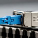
When you pick a transceiver, you are binding together wavelength, reach, optical budget, connector type, and temperature grade. For autonomous vehicles, you should also check DOM support (Digital Optical Monitoring), laser safety class, and whether the module is rated for vibration and automotive temperature ranges. Many integrators standardize on duplex LC for fiber patching, but harness constraints may push you toward MTP/MPO trunks or hardened breakouts. Vendor datasheets and Ethernet PHY requirements determine what will actually link up reliably.
Quick comparison: common module classes for vehicle networks
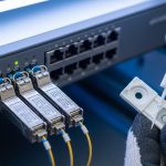
The table below summarizes typical choices used in autonomous vehicle deployments. Actual compatibility depends on your specific switch or NIC (SFP+/SFP28/QSFP+/QSFP28/QSFP-DD) and on the fiber plant.
| Module type | Typical data rate | Wavelength | Reach class | Connector | Typical power (class) | Temperature range (target) | Common DOM |
|---|---|---|---|---|---|---|---|
| SFP+ | 10G | 850 nm (SR) | ~300 m OM3 / ~400 m OM4 | LC duplex | ~0.8–1.5 W | -20 to +70 C (industrial) or wider automotive grade | Yes, per vendor |
| SFP28 | 25G | 850 nm (SR) | ~70 m OM3 / ~100 m OM4 | LC duplex | ~1.2–2.0 W | -20 to +70 C (industrial) or wider automotive grade | Yes, per vendor |
| QSFP28 | 25G (4 lanes) | 850 nm (SR) | ~100 m OM4 class | MPO/MTP or LC breakout | ~3–4.5 W | -20 to +70 C (industrial) or wider automotive grade | Yes, per vendor |
| QSFP28 / QSFP-DD | 100G (varies by lane) | 850 nm or 1310/1550 nm (SR/LR/ER) | From ~100 m to kilometers depending on optics | MPO/MTP or LC | ~6–10 W | Depends heavily on vendor and grade | Yes, per vendor |
Examples you may see in real shops include Cisco SFP-10G-SR and Finisar FTLX8571D3BCL for 10G SR-class behavior, plus FS.com and other suppliers offering compatible SR optics in similar form factors. Always verify the exact vendor part number against your switch/NIC compatibility list and DOM behavior.
Operating temperature and thermal derating
Even if a transceiver “links,” it may degrade under sustained heat soak. In vehicle enclosures, internal airflow is limited; you should plan for both ambient and module case temperature. Many modules specify temperature ranges like -20 to +70 C for industrial units, while automotive-grade options may extend further. If you cannot get automotive-grade, enforce derating: lower maximum transmit power operation and validate with thermal chamber testing.
DOM and what to monitor
Digital Optical Monitoring (DOM) commonly reports transmit laser bias current, laser output power, received optical power, and sometimes temperature. In operations, you use these telemetry points to detect fiber contamination trends and to forecast link margin loss before a link drops. For safety-critical autonomy stacks, treat DOM alarms as maintenance tickets, not as “informational.”
Selection checklist: choosing optics that survive the vehicle reality
Use this ordered checklist to avoid the most common “it worked in the lab” failures. The goal is to ensure your optical budget, mechanical fit, and compatibility all align with the host hardware and the fiber plant. If you standardize across your fleet, you also reduce spares complexity and shorten field swap time.
- Distance and fiber type: Measure end-to-end length and confirm OM3 vs OM4 (and connector cleanliness). Add a margin for patch cords and harness slack.
- Link budget and operating margin: Compare vendor specs for minimum received power versus your estimated link loss (including connectors, splices, and aging margin).
- Host compatibility: Confirm the host switch/NIC supports the module form factor and speed mode (SFP+/SFP28/QSFP28/QSFP-DD). Check vendor compatibility matrices.
- Connector strategy: LC duplex for short patching, MPO/MTP for high-density trunks. For vibration, use hardened ferrules and strain relief.
- DOM support and alarm thresholds: Verify DOM is enabled and that telemetry is readable by your monitoring stack.
- Operating temperature and derating plan: Validate worst-case enclosure temperature, then apply derating if you are not using automotive-grade parts.
- Laser safety and regulatory constraints: Ensure the module’s class and wavelength are acceptable for your installation and maintenance procedures.
- Vendor lock-in risk and spares strategy: OEM optics may cost more but can reduce downtime. Third-party optics can work, but require qualification and DOM validation.
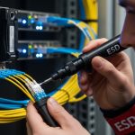
Pro Tip: In field deployments, the single biggest “mystery link-down” cause is not the transceiver—it is connector contamination plus micro-movement. Train your team to clean, inspect, and re-test with a consistent procedure, and use DOM received power telemetry to catch gradual margin loss before a hard failure.
Real-world deployment scenario: 10G optics in a 3-tier autonomous vehicle compute stack
Consider a 3-tier architecture inside a vehicle: edge sensor hubs connect to a rugged top-of-rack switch, which then connects to two redundant compute nodes running perception pipelines. In one deployment, the sensor tier uses 10G SR optics over a mixed harness: 18 m average distance per link, with 2 LC connectors and 1 splice per path. Engineers target OM4-rated cabling for margin, then allocate an extra 3–4 dB for assembly variability and aging. The result is stable link bring-up and predictable maintenance windows using DOM thresholds for received power drift.
In the same program, the roadside uplink uses a different profile: 25G or 100G optics in a depot or roadside cabinet, where enclosure temperatures are higher but distances are longer. Teams plan for higher optical budget requirements and validate that the switch’s optics support the exact module type. When a transceiver fails, technicians swap a module in under 10 minutes using pre-labeled spares, then confirm link stability by checking DOM readouts and verifying error counters.
Common pitfalls and troubleshooting tips (what actually breaks)
Below are concrete failure modes you can expect in autonomous vehicle optics programs. Each entry includes the root cause and what to do next. If you build a repeatable fault workflow, you cut mean time to repair (MTTR) and avoid repeated swaps that don’t fix the underlying issue.
Link comes up intermittently during vibration
Root cause: Connector ferrule contamination or poor strain relief causes micro-misalignment under vehicle vibration. Even a tiny particle can reduce coupling efficiency and push the link below the receiver sensitivity threshold.
Solution: Clean and inspect both ends using proper fiber cleaning tools, then re-seat with strain relief. Use DOM received power telemetry to confirm margin recovery; if margin remains low, replace the patch cord or connector assembly.
“Works on bench” but fails in enclosure thermal soak
Root cause: The module is rated for a narrower temperature range than the actual case temperature in the vehicle. Laser power and receiver sensitivity can drift, and some modules may enforce internal protection behavior.
Solution: Run a thermal chamber test at the worst-case enclosure temperature with the real harness. If needed, switch to automotive-grade parts or apply derating by configuring lower transmit power (where supported) and verifying link stability.
DOM shows alarms, but the switch reports no physical errors until later
Root cause: Monitoring thresholds are not aligned with your operational margin. DOM can reveal slow degradation (aging laser output, gradual contamination), but your monitoring stack may not convert those signals into actionable alerts.
Solution: Define DOM alarm thresholds based on your link budget and measured received power distribution. Create a maintenance workflow: when received power drops by a set delta, schedule cleaning or connector service before link drop occurs.
Host compatibility mismatch (module recognized but link never stabilizes)
Root cause: The transceiver is not truly compatible with the host PHY settings or optics profile, even if the form factor matches. Some hosts require specific electrical characteristics or vendor-specific calibration behavior.
Solution: Verify compatibility using the host’s approved optics list. If you must use third-party modules, qualify them with your exact switch/NIC and firmware version, and confirm DOM and link negotiation behavior.
Cost and ROI: how to budget optics for autonomous vehicle scale
Pricing varies widely by speed, reach, and grade. As a rough field estimate, 10G SR SFP+ optics often land in the tens to low hundreds of dollars per module, while 25G/100G optics typically cost more, especially when you require wider temperature grading and extended qualification. OEM optics can reduce integration risk but increase bill of materials (BOM) cost and lead-time sensitivity.
ROI comes from reduced downtime and fewer truck rolls. If your program runs thousands of vehicles, even a small improvement in MTTR and failure rate can outweigh higher module unit cost. Total cost of ownership (TCO) should include cleaning consumables, inspection tools, spares inventory, and qualification testing time. For example, qualification that prevents one systemic incompatibility issue can save weeks of rework and avoid a cascade of replacement swaps.
FAQ: optical transceivers for autonomous vehicles
Do autonomous vehicles need fiber for every link?
No. Many teams use fiber for longer runs, EMI-sensitive connections, and high-bandwidth aggregation while keeping short, low-speed links on copper. The best approach is to map distance, noise exposure, and reliability targets per segment, then choose optics only where the trade-off wins.
Which is better for vehicle networks: LC duplex or MPO/MTP?
LC duplex is easier to patch and inspect during field service, which helps when you are troubleshooting. MPO/MTP improves density and can reduce harness bulk, but it requires disciplined polarity management, careful cleaning, and standardized breakout hardware.
How important is DOM for autonomous vehicle operations?
DOM is very important when you want predictive maintenance. Received power trends and laser output drift help you detect contamination or aging before a link fails. If your monitoring stack cannot read DOM, you lose much of the operational advantage.
Can I use third-party optics in an OEM switch?
Often yes, but you must qualify them with your exact host model and firmware. Verify compatibility, DOM behavior, and link stability under your thermal and vibration conditions. If you skip qualification, you risk intermittent bring-up or late failures that cost more than the savings.
What is the most common reason optics fail in the field?
Connector contamination and micro-movement are the top causes in many deployments. Laser and receiver faults happen, but they are usually less frequent than cleaning and mechanical strain issues. Build a cleaning-and-inspection workflow and tie it to DOM alarms.
How do I estimate optical reach for a vehicle harness?
Start with the module’s vendor reach class, then subtract estimated losses from connectors, splices, and patch cords. Add aging and assembly tolerance margin, then validate with a measured received power baseline in your environment. Do not rely only on “rated reach” claims.
If you want to go deeper into how to structure the network and monitoring for autonomy stacks, see autonomous vehicle networking. For hands-on fiber handling and inspection routines, pair this guide with fiber optic transceiver and a reliability workflow focused on error counters and DOM telemetry.
Updated: 2026-05-04. I’m a clinician-turned-network reliability writer who consults on safety-critical system design and the practical failure modes that show up after deployment, not just during lab validation. I focus on measurable link budgets, operational monitoring, and field-ready troubleshooting workflows for teams building autonomous vehicles.