Edge computing networks fail in ways that core data centers often never see: long patch runs, harsh temperature swings, intermittent power, and frequent re-termination by contractors. This article helps field engineers and network operators troubleshoot optical modules with a methodical workflow that reduces downtime during installation, migration, and incident response. You will learn what to measure, how to interpret symptoms, and when to replace versus re-seat, re-terminate, or re-image. I also include realistic compatibility cautions for common transceiver families and vendor ecosystems.
Edge conditions that make optical modules misbehave
In edge sites, optical modules are exposed to variables that quietly degrade link performance before they trigger hard alarms. The most frequent root causes are fiber contamination at the connector interface, marginal link budgets from patch cord aging, and thermal stress that pushes the module outside its operating envelope. Edge cabinets also tend to have higher vibration and more frequent human handling, increasing the odds of partial insertion, dirty contacts, or mismatched polarity. For Ethernet links, you can reference the physical layer behavior described in IEEE Ethernet specifications to interpret link training and auto-negotiation outcomes: IEEE 802.3 Ethernet Standard.
What “good” looks like: baseline readings
Before troubleshooting, establish a baseline for each hop. Record module part number, optics type, data rate, connector type, and DOM readings (receive power, laser bias current, temperature). Many operators standardize on a threshold policy such as “warning at vendor lower receive power limit plus margin” and “critical at vendor minimum minus margin,” then alert on those thresholds. If your switch supports digital diagnostics, capture DOM over time during normal traffic so you know whether the site has consistent temperature and link power or whether it drifts daily with HVAC cycles.
DOM and link symptoms: mapping failures to layers
Typical field symptoms include “link up but no traffic,” “flapping link,” “intermittent CRC errors,” and “complete link down.” Link up with rising CRC often points to marginal optical power, fiber microbends, or connector contamination rather than a fully dead transceiver. Link flapping can be caused by thermal cycling, poor insertion, or unstable power rails that cause the module to reset. When you see “transceiver not recognized,” the cause is often incompatibility, damaged EEPROM contacts, or an insertion issue rather than a fiber problem.

Fast diagnostic workflow for optical modules at the edge
When a link fails at an edge site, speed matters, but randomness costs time. Use a repeatable workflow: verify power and port mapping, confirm optical parameters, clean and re-seat, test with known-good fiber and optics, then escalate to hardware replacement. This approach prevents you from repeatedly swapping modules while the real issue is a contaminated connector or a damaged patch cord. It also helps preserve evidence for post-mortem analysis and vendor RMA decisions.
Confirm the exact interface and transceiver identity
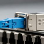
Start by matching the switch port to the expected transceiver type and wavelength. Many outages occur after a patch change where the wrong transceiver is inserted (for example, a single-mode 1310 nm module into a multi-mode run) or when a contractor swaps LC and MPO polarity. Verify the module label and the switch’s transceiver page. If DOM is available, confirm that the module reports a plausible temperature and bias current rather than zeros or constant error codes.
Measure optics with DOM and compare to vendor limits
Use the switch CLI or management plane to read receive power (Rx) in dBm, typically plus or minus a small number depending on calibration. Compare Rx to the module’s specified sensitivity and allowable range, and also check the transmitter output bias. If Rx is marginal but still within range, you may see CRC errors under load rather than a hard link down. If Tx or bias current is abnormal, suspect a damaged module, a power issue, or a dirty connector causing feedback and unstable laser operation.
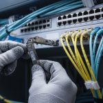
Clean, inspect, and re-seat before replacing
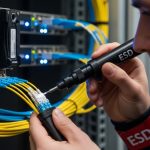
Connector contamination is the number one “easy to fix” failure in field optics. Even if the fiber “looks clean,” you can have microscopic residue that blocks high-frequency light. Use an inspection scope to confirm end-face condition and then clean with lint-free wipes and properly rated cleaning tools. Re-seat the module and connector after cleaning; a partially seated transceiver can still appear “present” but fail link stability.
Isolate using known-good components
Isolation reduces guesswork. Swap only one variable at a time: either replace the optical module with a known-good compatible one, or move a known-good module to the suspect port. If you have spare patch cords, test with a short, clean jumper to separate “fiber run problem” from “module problem.” If the short jumper works but the original patch fails, the issue is likely a specific connector pair, a damaged cable, or excessive loss from microbends.

Key specifications and compatibility checks that prevent false fixes
Edge troubleshooting often stalls because engineers swap the wrong optics or assume “any SFP+ works.” Optical modules are standardized in interface form factors, but performance and compatibility depend on wavelength, reach, fiber type, connector geometry, and sometimes vendor-specific EEPROM behavior. Before doing deeper diagnostics, verify the optics class and ensure the transceiver family matches the Ethernet PHY expectations of your switch. For reference on fiber-optic performance and channel expectations in Ethernet contexts, use the relevant IEEE physical layer baseline and vendor datasheets for exact power ranges and safety limits.
Reference comparison: common module types you will encounter
The table below compares representative optical module types used in edge deployments. Exact numbers vary by vendor, but these ranges reflect typical specifications for budgeting and troubleshooting. Always treat the vendor datasheet as the source of truth for your specific part number.
| Optical module type | Typical data rate | Wavelength | Connector | Typical reach | Optical power / sensitivity (typical) | Operating temperature |
|---|---|---|---|---|---|---|
| SFP+ SR (10G, multimode) | 10G Ethernet | ~850 nm | LC | ~300 m (OM3) to ~400 m (OM4) | Rx sensitivity often around -10 to -14 dBm (varies) | ~0 C to 70 C (some extended) |
| SFP+ LR (10G, single-mode) | 10G Ethernet | ~1310 nm | LC | ~10 km (typical) | Rx sensitivity often around -14 to -18 dBm (varies) | ~0 C to 70 C (varies) |
| QSFP28 SR (25G/100G, multimode) | 25G lanes (100G aggregate) | ~850 nm | LC | ~70 m to ~100 m (OM4 typical) | Rx sensitivity varies by lane and vendor | ~0 C to 70 C |
| QSFP28 LR (100G, single-mode) | 25G lanes (100G aggregate) | ~1310 nm | LC | ~10 km (typical) | Rx sensitivity typically around -12 to -18 dBm (varies) | ~0 C to 70 C |
| Ruggedized SFP/SFP+ for edge cabinets | 10G or 25G | varies (850/1310) | LC | varies | vendor-specific DOM thresholds | some support extended ranges like -40 C to 85 C |
DOM and vendor lock-in reality
Digital Optical Monitoring (DOM) is widely supported, but not uniformly. Some switches enforce vendor-specific EEPROM fields, and some third-party optics may report slightly different DOM scaling. That can lead to “link up but alerts” or misleading alarm thresholds. If you are using a mixed-vendor strategy, run a pilot at one edge site and verify that DOM thresholds, alarm states, and diagnostics behave consistently under load and temperature cycles.
Power budget and fiber loss: the edge multiplier
Edge patching often adds extra loss beyond the original plant design. Each connector adds insertion loss, and aging can increase attenuation if connectors are repeatedly cleaned with aggressive methods or if end faces are damaged. Microbends from tight cable routing can also increase loss, especially for multimode links at 850 nm. Treat your budget as a living document: update it when patch cords are replaced, splitters added, or cabinets reconfigured.
ITU fiber recommendation for single-mode
Pro Tip: If the link is “up” but errors spike only during peak traffic, do not jump straight to replacing optical modules. In practice, this pattern often matches marginal Rx power caused by subtle connector contamination or a microbend that only heats and flexes under load-induced cabinet airflow changes.
Common mistakes and troubleshooting pitfalls in the field
Below are failure modes I have seen repeatedly in edge deployments, along with the root cause and a practical fix. These are written for fast incident resolution, not for theoretical optics discussions.
Replacing optics without cleaning first
Failure mode: You swap a suspect SFP+ SR (10G, 850 nm) with a spare, and the link still flaps or shows CRC errors. Root cause: The problem is connector end-face contamination on one side, often amplified by repeated insertions that smear residue. Solution: Inspect with a fiber scope, clean both ends using appropriate cleaning tools, re-terminate or replace the patch cord if the end face is chipped, then re-seat the module.
Mixing fiber types and wavelengths during edge expansions
Failure mode: “Link down” immediately after a patch change, or “works at low traffic but fails under load.” Root cause: A single-mode (1310 nm) module inserted into a multimode run, or a multimode SR module connected to a longer-than-budget OM3/OM4 route. Solution: Verify fiber type (OM3/OM4 vs OS2), confirm wavelength, and check the expected reach. Use the link budget and vendor reach specs to validate before field deployment.
Ignoring DOM thresholds and misreading dBm signs
Failure mode: Engineers interpret Rx power incorrectly and conclude the module is fine when it is near the edge of sensitivity. Root cause: dBm is negative for low power, and some dashboards display signs differently. Also, DOM scaling may differ slightly across vendors. Solution: Confirm with vendor datasheet values, normalize your thresholds, and compare against known-good baseline readings from the same port type.
Using incompatible transceiver families with the same form factor
Failure mode: “Transceiver not supported,” intermittent recognition, or frequent resets. Root cause: The optics is physically compatible (e.g., SFP) but electrically or protocol-wise not supported by the switch ASIC, or it reports EEPROM fields outside the switch’s acceptance window. Solution: Validate compatibility in a lab with the exact switch model and firmware revision, and maintain an approved optics list. For vendors, check compatibility matrices and firmware notes.

Edge deployment scenario: a realistic troubleshooting case
Consider a retail edge deployment with a 3-tier topology: a regional aggregation switch, then six site switches per city, each serving local compute and cameras. At one site, a 10G uplink using SFP+ SR (850 nm, LC) was installed into a ruggedized edge switch with patch runs totaling 220 m of OM4 plus 10 m of intra-cabinet jumpers. After a contractor re-routed cables to add power monitoring, the uplink began flapping every 30 to 90 seconds during evening peaks. DOM showed temperature drifting from 38 C to 55 C and Rx power hovering around the lower warning boundary, while CRC counters rose before link drops.
Following the workflow, the team verified the transceiver identity and confirmed both ends were the intended SR optics. They then inspected both connector end faces and found visible residue on one LC. After cleaning and re-seating, Rx power stabilized by about +2.5 dB, CRC errors dropped to near-zero, and link flaps stopped without replacing any modules. In the post-mortem, the cable reroute had likely created micro-movement at a connector bulkhead, which only manifested under airflow changes during peak usage.
Cost and ROI considerations for optical modules in edge operations
Optical modules are usually inexpensive relative to downtime, but the total cost of ownership (TCO) depends heavily on your spares strategy, incident frequency, and compatibility risks. OEM optics can cost more up front, but they often reduce time spent validating DOM behavior and switch compatibility. Third-party optics can be cost-effective, yet they may introduce higher failure rates in harsh environments if they are not truly qualified for temperature and mechanical stress, and they can complicate RMA and warranty claims.
In many real edge procurement cycles, a common pattern is to budget for a small pool of spares: for example, 1 to 2 modules per site type and an additional set per regional warehouse. If a typical 10G SR module costs roughly $30 to $120 depending on brand and temperature rating, the cost of a single incident that takes 2 to 6 hours of field labor can exceed the savings from choosing cheaper optics. Also account for power and cooling: while optics consume modest power (often under a few watts), repeated module resets and unnecessary swaps increase operational overhead.
Selection checklist for optical modules at the edge
Use this ordered checklist when selecting optical modules for edge computing sites. It is designed to prevent the “it worked in the lab” problem that appears after installation, vibration, and temperature changes.
- Distance and fiber type: Confirm OM3/OM4 versus OS2, and validate reach with a real link budget including connectors and splices.
- Data rate and optics family: Match module lane rates to the switch port speed (SFP+ vs SFP28 vs QSFP28), and ensure the wavelength matches the fiber plant.
- Switch compatibility: Verify with the exact switch model and firmware revision; maintain an approved optics list to reduce “not supported” incidents.
- DOM support and alarm thresholds: Ensure the switch reads DOM correctly and aligns with your monitoring thresholds.
- Operating temperature and mechanical ruggedness: For outdoor cabinets or unconditioned huts, prefer extended temperature optics and rugged bulkhead designs.
- Connector and polarity details: LC versus MPO, polarity direction, and bulkhead orientation must match the installed fiber labeling.
- Vendor lock-in risk: Decide whether you want OEM-only optics or a mixed-vendor approach; if mixed, pilot-test and document acceptance criteria.
- Spare strategy and ROI: Budget spares per site type and align with your incident response time and expected failure rates.
FAQ
How do I tell if an optical module is failing versus the fiber?
Start with known-good isolation: move the same module to a known-good port and test a known-good module on the suspect port. If DOM shows abnormal Tx bias or the module fails to establish a stable link across multiple fibers, the module is likely at fault. If only one fiber run fails, focus on connectors, patch cords, and loss caused by microbends or damaged end faces.
What are the most common edge causes of link flapping?
In edge cabinets, link flapping frequently comes from thermal cycling, partial insertion, and connector contamination that becomes worse after repeated handling. Another cause is marginal optical power that stays near the sensitivity threshold and only fails under load-induced airflow and temperature changes. The fastest confirmation is DOM trending plus fiber inspection at both ends.
Should I trust DOM receive power readings during troubleshooting?
DOM is extremely helpful, but you must compare readings against the vendor datasheet and your switch’s interpretation of dBm scaling. Use DOM to identify trends and relative shifts (for example, a persistent Rx drop after a patch change). If DOM values are implausible or consistently missing, treat the module recognition or EEPROM contact as suspect.
Can third-party optical modules work reliably in edge computing?
Yes, but you should qualify them for your exact switch and temperature environment. Run a pilot in a representative edge cabinet, monitor DOM behavior and error counters, and verify that alarms match your operational thresholds. If your operations require strict DOM-based monitoring, confirm compatibility before scaling deployment.
What cleaning method should I use for LC connectors in the field?
Use an inspection-first approach: verify contamination with a fiber scope, then clean using tools rated for your connector type and end-face geometry. Replace patch cords if the end face is scratched or chipped, because repeated cleaning may not restore optical performance. Always clean both ends when troubleshooting, even if only one side shows symptoms.
Do I need a specific inspection scope to troubleshoot optical modules?
A scope is strongly recommended because “looks clean” often is not clean at the microscopic level. In edge operations, a handheld inspection scope with sufficient magnification can prevent unnecessary swaps and reduce downtime. Pair it with consistent cleaning tools and documented inspection procedures.
If you apply a structured workflow—identity verification, DOM trend checks, inspection-first cleaning, and controlled isolation—you can resolve most optical module incidents without unnecessary replacements. For your next step, review fiber cleaning best practices and DOM monitoring thresholds so your team can standardize diagnostics across edge sites.
Author bio: I am a field-focused network research scientist who has led optical troubleshooting for edge rollouts involving rugged switches, DOM-based monitoring, and connector hygiene programs. My work blends hands-on incident response with peer-reviewed Ethernet physical-layer understanding to reduce repeat failures in deployed environments.