In modern leaf-spine and campus backbones, optical module choice quietly determines network efficiency through power draw, thermal headroom, port density, and failure-domain design. This article helps IT directors and architects evaluate active versus passive optical modules using an enterprise lens: budget, ROI, architecture, and governance. You will also get practical troubleshooting patterns from field deployments, including DOM behavior, link budget gotchas, and compatibility constraints. optical-module-governance
Top 7 decisions that drive network efficiency with active vs passive optics

Optical modules are not interchangeable “widgets.” They change how much power is consumed per port, how optics are calibrated and monitored, and how quickly you can detect degradations before they become outages. For governance, you also need predictable interoperability and documented acceptance criteria. For ROI, you need realistic TCO math: optics are a small BOM line item, but they influence switch thermals, cooling energy, and mean time to repair.
Power per port and thermal density: the hidden lever
Network efficiency starts at the rack. Active optical modules (with integrated transceiver electronics) generally consume more power than passive optical modules (which typically rely on the switch’s or system’s external electronics). In practice, the difference shows up as higher watts per port, which can force airflow changes, increase fan speeds, and reduce usable cable management space. IEEE 802.3-compliant Ethernet links define electrical and optical signaling behavior, but the platform still has to supply power and dissipate heat. IEEE 802.3 Ethernet Standard
What to measure in the field
During a 10G and 25G migration, I typically record three values per switch model: (1) module power draw at steady state, (2) inlet air temperature at the top-of-rack, and (3) fan duty cycle under load. A common pattern is that 25G active optics in high-density ports can raise inlet temperatures by 1 to 3 C in constrained racks, which then increases fan energy. Passive optics often keep thermals flatter, but you must validate that the host switch supports the required optical interface and power budget.
Best-fit scenario: If you run 48- or 96-port ToR switches at high utilization with tight cold-aisle limits, active modules can still be viable, but you must budget thermal headroom and cooling costs. Passive modules often win when the host platform already provides the right electronics and you want predictable power.
- Active pros: more integrated monitoring and sometimes better reach optimization.
- Active cons: higher power draw; may reduce achievable port density.
- Passive pros: lower power; helps thermal efficiency.
- Passive cons: depends more on host electronics; monitoring may be limited.
Optical reach and link budget: distance efficiency vs margin risk
Network efficiency is also about how many meters (or fiber segments) you can cover without overbuying. Active optics can be tuned to support longer reaches in certain architectures by including more sophisticated transmit and receive electronics. Passive optics, such as fiber cabling plus splitters or certain passive assemblies, can be efficient but are more sensitive to insertion loss, connector cleanliness, and aging. Either way, you need to validate the link budget: transmitter power, receiver sensitivity, fiber attenuation, and connector/splice losses.
Typical reach expectations you must validate
For Ethernet transceivers, reach varies with wavelength, modulation format, and optics class. For example, 10G SR uses MMF at 850 nm and is generally short-reach, while LR at 1310 nm supports longer distances over SMF. Active versus passive does not replace the physics: budget and margin still govern whether the link will stay up during temperature swings and after connector re-matings.
Best-fit scenario: Choose active modules when you need reach flexibility across mixed fiber types or when the host platform supports the module class with sufficient optical margin. Choose passive assemblies when the fiber plant is already standardized, tested, and maintained with strict cleaning and splice-loss control.
- Active pros: often better tolerance via integrated optics/electronics.
- Active cons: still limited by vendor-defined optical budgets and temperature ranges.
- Passive pros: minimal electronics, stable behavior if the plant is clean.
- Passive cons: insertion loss and contamination can dominate.
Compatibility and interoperability: governance for network efficiency
Enterprise network efficiency depends on how many exceptions your operations team must manage. Active modules can be more sensitive to platform compatibility because the host may enforce vendor-specific transceiver behavior, power levels, or diagnostics. Passive solutions can still face compatibility issues when the host expects a particular optical interface type, connector geometry, or DOM support profile. The governance question is not “Will it light up once?” but “Will it remain within acceptance criteria across swaps, firmware changes, and RMA replacements?”
DOM and diagnostics as a governance gate
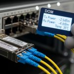
DOM (Digital Optical Monitoring) is a key factor for operational efficiency. Many active transceivers expose RX power, TX bias current, and module temperature via I2C/MDIO-like management paths. Passive assemblies may not provide these signals at the module level. If your NOC relies on threshold alarms to catch degradation, DOM availability becomes a hard requirement for network efficiency. In practice, I enforce acceptance criteria: DOM must populate fields in the switch CLI, alarm thresholds must be configurable, and readings must remain within vendor-recommended tolerances during burn-in.
Best-fit scenario: If your governance model requires automated optical health monitoring and standardized alerts, prioritize active modules with consistent DOM behavior. If monitoring is handled elsewhere (for example, fiber plant monitoring) and the host is standardized, passive approaches can reduce operational complexity.
- Active pros: richer telemetry and faster diagnosis.
- Active cons: potential vendor lock-in; compatibility matrices matter.
- Passive pros: simpler optics; fewer electronics to fail.
- Passive cons: weaker per-link telemetry if no DOM exists.
A comparative specs table you can use for procurement
Procurement teams often compare modules by marketing reach alone. For network efficiency, you need a structured view of electrical and optical properties, diagnostics, and environmental constraints. Below is a practical comparison table focused on what most data center engineers and IT directors care about when evaluating active versus passive approaches for Ethernet optics. Exact values vary by vendor and part number, so treat this as a procurement checklist scaffold rather than a guarantee.
| Spec category | Active optical module (typical transceiver) | Passive optical approach (typical assembly/cabling) |
|---|---|---|
| Data rate classes | Common: 1G, 10G, 25G, 40G, 100G (vendor and form factor dependent) | Dependent on endpoint electronics; passive assemblies do not set modulation format |
| Wavelength examples | MMF: 850 nm; SMF: 1310 nm or 1550 nm | Dependent on the system optics; passive elements are wavelength-sensitive only by design |
| Reach (typical) | SR: short reach; LR: longer reach; exact meters depend on fiber type and class | Dependent on insertion loss and fiber plant; splitter/patch loss can dominate |
| Connector types | LC/SC style common; must match transceiver and fiber patching standards | LC/SC or custom assemblies; mechanical compatibility still critical |
| Diagnostics | Often includes DOM: TX/RX power, temperature, bias current | May lack per-link DOM; telemetry may be external or absent |
| Power draw | Higher per-port than passive; budget watts and thermal headroom | Lower at the optical layer; power savings depend on host architecture |
| Operating temperature | Vendor-defined ranges; often wider for enterprise SKUs | Depends on the passive assembly materials and any integrated components |
| Failure mode profile | Electronics and optics failures; can be diagnosed via DOM | Connector contamination, splice loss increases, mechanical wear |
| Governance fit | Requires documented compatibility and alarm thresholds | Requires fiber plant standards and cleaning/splice governance |
Best-fit scenario: Use this table to standardize a bid comparison across vendors and to align your network efficiency goals with measurable procurement criteria such as diagnostics coverage, thermal impact, and environmental support.
- Active pros: telemetry and often predictable electrical behavior.
- Active cons: power and compatibility constraints.
- Passive pros: simpler optics stack; lower optical-layer power.
- Passive cons: plant issues become more visible only after outages or margin collapse.
Real-world deployment scenario: where network efficiency shows up as uptime
In a 3-tier data center leaf-spine topology with 48-port 10G ToR switches feeding 2x 100G uplinks per ToR, we migrated 10G server connections to 10G SFP+ SR optics while standardizing uplink optics for consistent operational behavior. The environment had hot-aisle containment with inlet temperatures capped at 24 C, and we tracked thermal events that correlated with higher module power. For downlinks, we selected vendor-matched active transceivers for DOM visibility; for certain patching runs, we used passive patch assemblies with strict connector cleanliness controls and validated insertion loss. After the change, optical alarms caught a gradual RX power drift on three uplinks weeks before any link flap, reducing mean time to repair and improving network efficiency as measured by fewer escalations and faster containment.
Best-fit scenario: If your operations team uses telemetry-driven incident response, active modules with DOM typically improve network efficiency by accelerating root cause analysis and preventing cascading failures.
- Active pros: earlier detection via DOM; faster triage.
- Active cons: higher power; compatibility validation required.
- Passive pros: stable if fiber plant is controlled; low optical-layer power.
- Passive cons: troubleshooting can be slower without per-link optics telemetry.
Cost and ROI: TCO math beyond the per-module price
Active modules often cost more upfront than passive optical components or assemblies, but ROI depends on the full lifecycle. Active transceivers may reduce labor time during troubleshooting due to DOM telemetry and can reduce downtime by catching degradation early. Passive approaches can reduce power and sometimes simplify procurement, but they shift cost into fiber plant maintenance: cleaning, inspection, re-termination, and insertion-loss management. In TCO models, I include: module purchase price, estimated failure rate, expected labor hours per incident, and cooling energy impacts from higher power draw.
Practical price ranges and what they usually imply
In enterprise procurement, third-party optics can be significantly cheaper than OEM, but the savings can evaporate if compatibility issues cause non-compliant behavior, increased returns, or delayed upgrades. As a rule of thumb, OEM transceivers for mainstream Ethernet form factors may carry a premium that funds validation and predictable diagnostics. Third-party units vary widely: some match OEM behavior closely, while others have partial DOM implementation or inconsistent thermal calibration. If your governance requires strict interoperability tests, you should budget time for a pilot batch and acceptance verification before scaling.
Best-fit scenario: If your network efficiency goals include minimizing operational risk and downtime, prioritize predictable telemetry and compatibility, even if unit costs are higher. If your fiber plant is already mature and you have tight operational processes, passive assemblies can deliver net savings through reduced power and fewer electronics to fail.
- Active pros: improved mean time to diagnose; potential downtime reduction.
- Active cons: higher power and possible platform lock-in.
- Passive pros: lower optical-layer power; fewer electronics.
- Passive cons: higher reliance on fiber plant hygiene; less per-link visibility.
Troubleshooting and common pitfalls: what fails and why
Network efficiency degrades when optics failures become recurring or when troubleshooting consumes time. Active and passive approaches tend to fail in different ways, so you need targeted playbooks. Below are common failure modes I have seen in real operations, with root causes and practical solutions.
Pitfall 1: DOM fields missing or thresholds not triggering
Root cause: The switch platform may not fully support the vendor’s DOM implementation, or the transceiver is partially compatible with the host’s management expectations. Sometimes the module powers up but DOM registers are incomplete.
Solution: Validate DOM availability during acceptance testing. Confirm that RX power, TX bias, and module temperature are readable in the switch interface and that alarms can be configured. If DOM is missing, network efficiency suffers because you lose early warning.
Pitfall 2: Link flaps after re-patching due to connector contamination
Root cause: Passive assemblies and even active transceivers can fail intermittently when connector endfaces are contaminated. Even a single re-mate with dirty LC/SC ends can add enough loss to push the link past margin.
Solution: Enforce a cleaning and inspection workflow. Use an endface inspection scope for every re-termination and adopt a “clean before connect” policy. Track insertion loss changes if your environment supports it.
Pitfall 3: Thermal throttling or marginal operation under high ambient load
Root cause: Active optics increase per-port power and heat in high-density ports. If airflow is constrained or if racks run closer to maximum inlet temperature, optics can drift toward the edge of their operating envelope.
Solution: Correlate optical errors with inlet temperature and fan duty cycle. Apply airflow improvements first, then verify that transceivers meet the platform’s supported temperature class. Retest under peak load after any cooling changes.
Pitfall 4: Fiber type mismatch hidden by “it lights up” testing
Root cause: Using the wrong fiber type or patch cord polarity can sometimes produce a marginal link that fails under certain traffic patterns or after temperature changes. MMF/SMF mismatches are a common root cause in mixed plant environments.
Solution: Confirm fiber type and patch maps before installation. Validate link budget with measured attenuation where possible and ensure polarity and connector standards match the transceiver requirements.
Pro Tip: In many enterprise environments, network efficiency improves more from operational visibility than from raw reach. If active optics provide DOM telemetry and your monitoring can alert on RX power drift early, you can prevent a slow degradation from turning into an outage that triggers manual interventions across multiple links.
Summary ranking table: which option best improves network efficiency?
Use this ranking table to guide an initial architecture decision. Final selection still depends on switch compatibility matrices, fiber plant maturity, and how your NOC monitors optics health.
| Evaluation area | Active optical modules | Passive optical approach | Best for network efficiency when… |
|---|---|---|---|
| Power and thermal density | Medium to lower efficiency (higher power) | Higher efficiency (lower optical-layer power) | Rack cooling is constrained or you need maximal port density. |
| Telemetry and diagnostics | Strong | Weak to moderate | You run alerting based on DOM-like measurements. |
| Interoperability governance | Medium (compatibility testing required) | Medium (depends on assembly and host expectations) | You can enforce acceptance criteria and maintain a compatibility matrix. |
| Link margin stability | Often better tolerance | Highly dependent on fiber plant hygiene | Your fiber plant is standardized and aggressively maintained. |
| Troubleshooting speed | Fast with DOM | Slower without per-link optics data | You need rapid root cause isolation during incidents. |
| Lifecycle cost and TCO | Higher unit cost, potentially lower downtime cost | Lower unit cost, higher plant maintenance risk | Your operational model supports strong fiber governance. |
For most enterprises targeting measurable network efficiency gains, the decision is not “active versus passive” in isolation; it is whether you can meet governance requirements for compatibility and monitoring while keeping thermal and link margins under control. If you want to tighten governance further, review optical-module-governance and align your acceptance tests with your monitoring and incident response workflows.
FAQ
Are active optical modules always better for network efficiency?
No. Active modules can improve operational efficiency through DOM telemetry and faster diagnosis, but they usually consume more power and can reduce achievable port density in thermally constrained racks. If your cooling margin is tight or you do not rely on optics telemetry, passive approaches may be more efficient overall.
Do passive optical assemblies support DOM diagnostics?
Often they do not provide module-level DOM telemetry because they may not include active transceiver electronics. In those cases, telemetry must come from external monitoring, host-side measurements, or separate fiber health tools, which can reduce how quickly you catch degradation.
What should we test during an optics pilot to protect network efficiency?
Validate: (1) DOM field visibility and alarm thresholds, (2) link stability under peak load and peak ambient temperature, and (3) behavior after re-patching. Also verify compatibility with your switch firmware and platform optics policies to prevent surprises during scale-out.
How do OEM and third-party optics affect ROI?
OEM optics typically reduce compatibility and validation risk, which can lower operational cost and return rates. Third-party optics can improve unit economics, but only if your acceptance criteria confirm DOM behavior, thermal compliance, and stable link performance in your exact fiber plant.
What are the fastest troubleshooting steps when links flap?
Start with connector cleanliness and inspection, then check DOM (if available) for RX power drift and temperature/bias anomalies. Next correlate events with airflow and inlet temperature, and finally verify fiber type, polarity, and patch map correctness.
Which form factor usually matters less than the active versus passive choice?
Form factor matters, but network efficiency usually hinges more on telemetry, power, and compatibility than on the physical shape alone. As long as the host supports the transceiver class and your governance tests pass, your architecture can still optimize efficiency based on operational visibility and thermal budget.
Updated on 2026-05-04.
Author bio: I am an IT director who has led multi-year data center migrations, including optics standardization, DOM-driven monitoring rollouts, and thermal governance for high-density racks. I evaluate vendor and third-party optics through compatibility matrices, acceptance criteria, and TCO models tied to uptime and incident response metrics.