A real commissioning issue in industrial automation is silent link failure: the controller boots fine, but the fiber port never negotiates, or sensors drop under vibration. This article helps engineers and system integrators compare a Keyence fiber module approach against SFP-style fiber transceivers used with Omron controller ecosystems. You will get practical compatibility checks, measurable optical and power considerations, and troubleshooting steps that field technicians can apply on-site.
How these industrial links behave in the real world
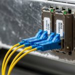
Industrial fiber links often mix two worlds: sensor-facing fiber modules (common in machine vision and fiber sensors) and switch/transceiver-style optics (commonly SFP modules). A Keyence fiber module is typically designed to match Keyence controller or sensor expectations for signal format, connector style, and link behavior. Omron deployments may use SFP optics in a broader Ethernet or managed-network context, or use fiber modules that integrate cleanly with Omron IO and controller cabling standards.
Before comparing specs, define the “signal type” your system expects. Many industrial setups use digital Ethernet over fiber, where the transceiver must support link training and proper line encoding at the target data rate. Other setups use sensor-specific digital or analog-over-fiber transport, where the module must match the proprietary timing and electrical interface of the controller family. This is why the same “fiber” word can hide very different requirements.
For standards grounding, Ethernet over fiber is defined in IEEE 802.3, including specifications for optical interfaces and reach classes. IEEE 802.3 Ethernet Standard

What engineers should verify first: interface, not optics
- Controller port type: SFP requires a host with an SFP cage and PHY expectations; a sensor module requires the matching Keyence or Omron fiber interface.
- Data rate: confirm whether you need 1G, 10G, 25G, or a sensor transport rate. Mismatched rates often show as “link up” but no usable traffic.
- Duplex and encoding: Ethernet usually uses 8b/10b (older generations) or 64b/66b (modern), while sensor transports may use different framing.
- Connector family: LC vs SC vs M12 fiber receptacles; adapter errors are frequent in plant retrofits.
Performance comparison: reach, wavelength, and link budget
Performance is not just “reach.” Two links can both work at commissioning but fail during long-term operation due to margin erosion from connector contamination, temperature drift, or aging optics. For Ethernet SFP optics, engineers typically care about wavelength (nm), nominal reach, transmit power, receive sensitivity, and allowable link loss.
For many industrial fiber sensors and controller modules, performance is often described as “operating distance” and “signal integrity,” but the underlying physics still follows link budget rules. The safe approach is to treat every fiber run as an optical channel with loss and reflections, then ensure your module’s power and sensitivity keep you within the margin.
Below is a head-to-head comparison using common SFP classes and the typical wavelength families you will encounter when integrating industrial fiber links. Note that exact Keyence and Omron module parameters depend on the specific part number and interface style.
| Option | Typical wavelength | Common reach class | Connector | Data rate examples | Operating temperature | Power draw (typical) |
|---|---|---|---|---|---|---|
| Keyence fiber module (controller-specified) | Varies by SKU; often 650 nm (short) or 850/1310 nm (fiber links) | From a few meters to campus-scale depending on SKU | Often LC or proprietary cage style depending on model | Sensor transport or Ethernet-like link (varies) | Often industrial -10 to 60 C; confirm datasheet | Small module draw; confirm SKU |
| Omron controller with SFP-style transceiver (Ethernet fiber) | 850 nm (SR) or 1310 nm (LR) | ~300 m (10G-SR typical) or more with LR | LC duplex for most SFP/SFP+ SR/LR | 1G, 10G, sometimes 25G with compatible cages | -5 to 70 C typical for many pluggables; confirm | ~1 to 4 W depending on class |
What to compute during link design
- Fiber attenuation: typical multimode OM3 around 3.0 dB/km at 850 nm; single-mode around 0.35 dB/km at 1310 nm (verify your fiber type).
- Connector and splice loss: include ~0.2 to 0.5 dB per connector and splice losses based on installation quality.
- Margin for contamination: plan for one cleaning event failure mode by keeping extra headroom (for field reality, margin matters).
- Budget for aging and temperature: link margin should survive seasonal temperature swings and dust accumulation.
For Ethernet optical interfaces, vendors often publish parameters aligned to IEEE 802.3 optical classes. Use the vendor datasheet for your exact transceiver model (for example, Cisco SFP-10G-SR, Finisar FTLX8571D3BCL, or FS.com SFP-10GSR-85) and match it to your fiber type and connector plan.

Compatibility: matching Keyence fiber module behavior to Omron controller requirements
Compatibility is where many projects stall. A Keyence fiber module can be “plug and play” inside a Keyence ecosystem, because the electrical interface and link expectations align with the controller firmware. Omron projects using SFP transceivers face a different risk: the host cage, PHY features, and firmware settings must match the transceiver’s signaling and negotiated speed.
In practice, engineers treat this as a three-layer compatibility problem: mechanical fit, electrical signaling, and software/firmware expectations. Even if the optics are correct, the host may reject the module, disable the port, or negotiate incorrectly.
Mechanical and optical compatibility checks
- Form factor: true SFP vs SFP+ vs other pluggable sizes; do not assume interchangeability.
- Connector standard: LC duplex is common for SR/LR, but industrial panels may use SC or M12; adapters introduce reflection and loss.
- Polarity and direction: duplex fiber wiring must match Tx/Rx pairs; swapped polarity can create “it powers but never passes data.”
Electrical and firmware checks
- DOM support: Digital Optical Monitoring data (laser bias, output power, RX power) may be required for alarms. Many industrial hosts log DOM thresholds.
- Speed and autonegotiation: configure fixed speed when supported; otherwise ensure the switch or controller port supports the same negotiation behavior.
- Vendor lock-in risk: some hosts enforce compatibility by reading EEPROM identifiers; third-party optics can work but may reduce alarm visibility or fail with strict policies.
When you integrate Ethernet over fiber into automation, you are still bound by the same Ethernet physical layer concepts described in IEEE 802.3, including how link establishment depends on correct optical signaling. ITU-T main portal
Cost and ROI for industrial fiber links: what to budget and why
Cost is not just the transceiver price. Total cost of ownership includes downtime risk, spares stocking, and the operational overhead of diagnosing “unknown unknowns” in the field. A Keyence fiber module is often priced higher than commodity optics, but it can reduce integration friction when you stay inside the Keyence ecosystem.
SFP optics for Omron-adjacent network architectures can be cost-effective when you standardize on a proven optics family and stock a small set of reach classes. However, ROI depends on failure mode rate, cleaning discipline, and how quickly you can swap spares during production interruptions.
Realistic price bands and TCO thinking
- Commodity third-party SFP modules: often lower unit cost, but verify DOM behavior and compatibility with the exact controller/switch host model.
- OEM optics: higher unit price, but typically better documentation, predictable DOM behavior, and fewer surprise compatibility issues.
- Hidden costs: labor time for re-termination, port troubleshooting, and production downtime often exceed the optics price by an order of magnitude.
In many plants, the ROI tipping point is not unit price; it is the time-to-recover during a fiber fault. If your team can replace a spares kit in under 15 minutes and restore service with pre-tested polarity and cleaning procedures, you can justify broader optics selection. If recovery takes longer, standardizing on the most compatible optics family becomes the safer investment.
Pro Tip: In field swaps, treat DOM alarms as a calibration signal, not just a health indicator. If RX power trends downward over weeks, schedule cleaning and fiber inspection before the port crosses the receiver sensitivity threshold; this “early maintenance” approach prevents the worst-case outage that usually happens when dust and temperature combine.

Decision matrix: Keyence fiber module vs SFP for Omron (engineer checklist)
Use the following ordered checklist during selection. It is written for engineers who must sign off on a design and support it months later, not just get a link working during a demo.
- Distance and fiber type: measure run length and confirm OM3/OM4 or single-mode. Choose wavelength class accordingly (850 nm for short multimode; 1310/1550 for longer single-mode).
- Data rate requirement: ensure the module supports your required throughput and framing. Confirm whether you need Ethernet-like transport or sensor-specific transport.
- Switch or controller compatibility: verify the exact Omron host model supports SFP cages, speed modes, and DOM behavior.
- DOM and monitoring: if your maintenance strategy relies on optical power alarms, confirm DOM is supported and thresholds are readable.
- Operating temperature: confirm transceiver/module temperature range matches the cabinet environment; many failures happen at hot spots near power supplies.
- Connector ecosystem and polarity plan: standardize LC duplex or your plant’s connector type; document polarity and adapter usage.
- Vendor lock-in risk: consider how easily you can source spares in emergencies. Stocking strategy can reduce lock-in pain more than you think.
- Testing and acceptance: plan link verification with a power meter and, if possible, OTDR for fiber runs. Document results for warranty and future troubleshooting.
Head-to-head decision matrix
| Criteria | Keyence fiber module fit | SFP for Omron fit | Best for |
|---|---|---|---|
| Fast integration in Keyence ecosystem | High | Medium | Machine vision and Keyence-centric control systems |
| Long-term maintainability with standard pluggables | Medium | High | Networked automation with standardized SFP spares |
| DOM-based predictive maintenance | Varies by module | Often strong | Teams with monitoring dashboards and alarms |
| Cost optimization for large fleets | Medium | High | Multi-line sites with consistent reach requirements |
| Risk of compatibility surprises | Lower inside ecosystem | Depends on exact host and policy | Brownfield retrofits where downtime is costly |
| Connector and polarity discipline | Usually simpler if standardized | Requires strict documentation | Sites with mature fiber management practices |
Common mistakes and troubleshooting tips for fiber links in Omron and Keyence setups
When something fails, engineers need a disciplined process. Below are field-proven failure modes with root causes and solutions, written for both SFP-style optics and Keyence fiber module integrations.
Link never comes up after swap
Root cause: wrong transceiver type for the host cage or wrong wavelength class for the fiber type (for example, using multimode-rated optics on a single-mode run or vice versa). Sometimes the host also blocks non-validated optics.
Solution: confirm the exact host model supports the specific SFP class, then match wavelength and reach to the fiber type. Measure fiber attenuation if possible and verify connector type and adapter usage.
Port appears up, but data is unreliable or intermittent
Root cause: contaminated connectors, degraded polishing, or dirty fiber endfaces causing marginal optical power. Temperature swings can push the link over the edge.
Solution: clean using proper lint-free wipes and cleaning tools, then inspect with a fiber microscope or inspection scope. Re-test optical power and replace patch cords if you see scratches or persistent contamination.
Works at the bench, fails in the cabinet
Root cause: thermal hotspots near power supplies or insufficient airflow, plus mechanical stress on fiber. Small bend radius violations can increase loss over time.
Solution: check cabinet airflow and confirm module temperature rating. Re-route fibers to maintain bend radius and add strain relief so connectors are not tugged during vibration.
SFP alarms show weak RX power even though link is stable
Root cause: aging optics or slow contamination buildup. This often starts as a warning, then becomes a full outage during the worst seasonal conditions.
Solution: schedule proactive cleaning and fiber inspection based on DOM trends. Keep a documented history of RX power and temperature for root-cause analysis.
Which option should you choose?
Choose a Keyence fiber module when you want the lowest integration risk inside a Keyence-led machine architecture, especially for sensor transport where module behavior is tightly coupled to controller expectations. Choose SFP for Omron when your project is Ethernet-centric, you need standardized pluggables across a fleet, and you can enforce strict compatibility and fiber hygiene practices.
If you are building a new line with consistent reach requirements and a mature spares strategy, SFP can deliver strong operational flexibility and scalable cost control. If you are retrofitting a brownfield system where downtime is unacceptable and compatibility uncertainty is the biggest threat, the Keyence fiber module path is often the safer first move. For deeper fiber handling practices, see fiber cleaning and inspection workflows.
FAQ
What exactly is a Keyence fiber module used for?
A Keyence fiber module is typically used to connect fiber-based sensors or to provide a fiber link that matches Keyence controller expectations. The exact function depends on the Keyence controller and the specific module part number.
Can I replace a Keyence fiber module with an SFP transceiver?
In most cases, you cannot treat them as direct substitutes. The controller interface and signaling expectations differ; an SFP may work only if the host supports the required optical and electrical interface for Ethernet-like transport.
How do I confirm compatibility with an Omron controller using SFP?
Start with the exact Omron controller or switch host model and confirm supported SFP types, data rates, and whether DOM monitoring is required. Then match wavelength and connector type to your fiber plan.
What are the most common causes of intermittent fiber faults?
Contaminated connectors, polarity swaps in duplex cabling, and thermal or mechanical stress are the top causes. Use an inspection scope and track optical power over time to catch marginal links early.
Are third-party SFP optics risky for industrial deployments?
They can be cost-effective, but risk depends on host enforcement policies and DOM behavior. If your maintenance process relies on predictable alarms, validate the optics with the exact host model before deploying at scale.
What tools should a field team keep for fiber troubleshooting?
A fiber inspection scope, a proper cleaning kit, and an optical power measurement approach are essential. For longer runs, OTDR or a link test plan helps confirm where loss is introduced.
Author bio: I design and validate industrial UI experiences and physical-layer workflows that reduce commissioning time and prevent downtime, with hands-on field troubleshooting habits. I focus on measurable acceptance criteria, clear operator affordances, and robust compatibility practices for fiber links and transceiver ecosystems.