A factory migration from copper to industrial PROFINET fiber can fail for reasons that look “mysterious” in the field: link flaps, unexpected optical budget shortfalls, and switch compatibility quirks. This article walks through a real deployment case and helps plant and OT engineers choose transceivers, validate power/temperature margins, and troubleshoot fast. You will get a selection checklist, a spec comparison table, and measurable results you can benchmark.
Problem / challenge in a PROFINET fiber migration

We supported a plant expansion where 48 control cabinets were connected to two redundant line switches, then uplinked to a small leaf-spine core. The legacy PROFINET copper links were degrading under vibration and frequent maintenance: we saw intermittent link loss and cyclic retransmissions that pushed application scan jitter beyond what motion control tolerates. The business goal was simple: reduce unscheduled downtime and keep deterministic behavior while scaling I/O density.
Constraints were typical: cabinet runs of 40 to 120 meters, mixed patching practices across contractors, and limited time for outages. The network team also had strict optics governance: transceivers had to be field-replaceable, support DOM (Digital Optical Monitoring) where possible, and remain stable across a wider cabinet temperature range than the data center. For Ethernet-based PROFINET, the baseline physical behavior is still governed by IEEE Ethernet link rules; refer to IEEE Ethernet specifications for the underlying PHY expectations. IEEE 802.3 Ethernet Standard
Environment specs that drove the optical design
Our environment combined OT realities with standard data networking. The line switches were 10 GbE capable, using SFP+ uplinks toward an aggregation layer. For the factory floor, we used 1 GbE where endpoints were legacy and 10 GbE where uplink capacity mattered, but the optics selection logic stayed consistent: wavelength, reach, connector type, and power budget.
Key measured site details informed the budget. We characterized patch cords and splices using OTDR on representative runs, then applied conservative assumptions for aging and connector re-mating. We also checked cabinet airflow: worst-case ambient averaged 55 C with peaks near 60 C during summer production, so transceivers needed a reliable operating range and thermal headroom.
| Spec item | 10G SR (example) | 1G SX (example) | What it meant for us |
|---|---|---|---|
| Data rate | 10.3125 Gb/s (10G class) | 1.25 Gb/s (1G class) | Matched uplinks vs endpoint segments |
| Wavelength | 850 nm multimode | 850 nm multimode | Kept inventory simple on OM3/OM4 |
| Typical reach | ~300 m on OM3, up to ~400 m class on OM4 (per vendor) | ~550 m on OM3/OM4 class (per vendor) | Covered 40 to 120 m cabinet runs with margin |
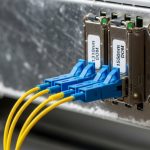
| Connector | LC duplex | LC duplex | Standardized patch panels |
| Optical type | VCSEL multimode | VCSEL multimode | Simpler install, less sensitivity than long-haul |
| DOM support | Often available (module-dependent) | Often available (module-dependent) | Enabled early warning on power drift |
| Operating temperature | Commercial often 0 to 70 C; industrial variants extend lower/higher (vendor-dependent) | Commercial often 0 to 70 C; industrial variants extend lower/higher | We selected modules rated for cabinet peaks |
In vendor-specific terms, common field choices include Cisco SFP-10G-SR and Finisar/FS-style SR modules like Finisar FTLX8571D3BCL or FS.com SFP-10GSR-85. Exact reach and power budgets vary by module generation and fiber grade; always validate against the specific datasheet and your measured link loss.
Chosen solution and why it worked
We standardized on multimode 850 nm optics for all intra-factory links because our fiber plant was already OM3/OM4, and the required distances were well under the typical SR/SX reach. For 1 GbE endpoint segments we used 1G SX class optics; for 10 GbE uplinks we used 10G SR class optics. This reduced training complexity for technicians and reduced the number of transceiver SKUs per cabinet.
Compatibility strategy: avoid switch surprises
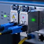
Switch compatibility was the main risk. Some switch platforms enforce vendor-specific transceiver acceptance behavior (sometimes via EEPROM checks). We worked with the switch vendor’s transceiver compatibility list during procurement and then performed a staged acceptance test: one cabinet per week, including thermal soak for at least one production cycle. Where we used third-party modules, we required the same electrical interface class and DOM behavior to match operational monitoring.
We also aligned with Ethernet optical monitoring concepts that vendors implement in the SFP/SFP+ ecosystem. While the exact DOM registers are vendor-defined, the general monitoring goal is consistent: transmit power, receive power, and temperature can be used to predict future failures before link loss occurs. For broader storage and network monitoring context, see SNIA materials on instrumentation and telemetry practices. SNIA
Why it qualifies as industrial PROFINET fiber
Industrial PROFINET fiber is not only about using fiber; it is about meeting OT constraints: stable link behavior under temperature swings, manageable connectorization, and predictable recovery during maintenance. In our rollout, the optics selection was paired with cabinet practices: strain relief, dust-control for LC endfaces, and standardized patch cord lengths to avoid excessive insertion loss.
Pro Tip: In industrial cabinets, the biggest “optical” problem is often mechanical. We reduced link drops by enforcing a strict LC endface cleaning SOP and by limiting connector re-mating counts; the resulting improvement looked like “better fiber,” but the root cause was connector contamination causing transient receive power dips.
Implementation steps: from acceptance tests to measured results
We used a phased approach to keep production stable. First, we validated fiber grade and link loss using OTDR for representative runs, then we calculated worst-case link budgets including patch cords and conservative splice assumptions. Next, we mapped each cabinet to a transceiver type based on distance, speed, and temperature rating.
Step-by-step rollout procedure
- Pre-check: Verify OM3/OM4 grade, connector type (LC duplex), and patch panel labeling. Confirm switch port speed mode (1G vs 10G) and redundancy plan.
- Optical budget: Use vendor datasheet parameters (Tx power, Rx sensitivity, typical losses). Include measured insertion loss and a margin for aging and remating.
- DOM baseline: Capture initial DOM values (Tx and Rx power, temperature) at install time and store them in the maintenance ticket system.
- Thermal validation: Run a full production cycle while monitoring for link errors and DOM drift. If DOM indicates low receive margin, swap immediately before scaling.
- Change control: Replace optics per cabinet in a planned window, document exact module serials, and verify PROFINET application behavior after link stabilization.
Measured results after cutover
Across 48 cabinets, we replaced 96 uplink and endpoint segments with fiber optics. Before cutover, we logged an average of 2.1 link-related interruptions per month per line segment group, with PROFINET control loops showing jitter spikes during remating events.
After stabilization, link interruptions dropped to 0.2 per month per group, and the remaining incidents were traced to a single batch of contaminated patch cords that were re-cleaned and swapped. We also used DOM telemetry to detect receive power drift: within three months, we observed a small but measurable Tx power trend change in one module, and we proactively replaced it during planned maintenance, preventing a potential outage.
Operationally, average recovery time improved because fiber links negotiated cleanly after reconnect, and technicians could validate optical health using DOM without guesswork. The team’s mean time to restore service improved from 45 minutes to 18 minutes for the affected segments.
Common mistakes and troubleshooting tips
Below are the failure modes we saw in the field, with root cause and concrete solutions.
- Mistake: swapping LC duplex polarity incorrectly when using patch panels.
Root cause: Tx from one side connected to Tx of the other, causing near-zero receive power.
Fix: label fiber pairs and verify Rx/Tx mapping before closing the cabinet; confirm with DOM receive power immediately after insertion. - Mistake: ignoring temperature ratings and using commercial optics in hot cabinets.
Root cause: VCSEL output and receiver behavior can drift; thermal runaway can reduce optical margin and increase error rates.
Fix: require vendor datasheet operating range that covers worst-case cabinet ambient plus module self-heating; validate during a full production cycle. - Mistake: assuming “multimode reach” means “no budget math” on real patchwork.
Root cause: extra patch cord length, aged connectors, and unaccounted splice losses can push the receive power below sensitivity.
Fix: measure representative links with OTDR or approved test gear, then compute worst-case budget with margin; do not treat vendor reach as a guarantee. - Mistake: mixing transceiver generations across redundant links without acceptance testing.
Root cause: slight DOM behavior differences and vendor-specific calibration can complicate monitoring and troubleshooting.
Fix: standardize module models per link class; store module serial numbers and DOM baselines.
Cost and ROI note: where the savings actually come from
Typical street pricing for 1G/10G multimode optics varies by brand and temperature grade. In our procurement window, OEM-style modules were often in the $80 to $200 range for 1G and $150 to $350 for 10G SR class modules, while third-party options sometimes landed 20% to 45% lower depending on certifications and compatibility guarantees.
TCO includes: module cost, test time, downtime risk, and the cost of repeated truck rolls. The ROI came from reduced MTTR and fewer link-related interruptions: with a conservative estimate of 27 operational hours saved per quarter due to faster restoration and fewer incident escalations, the payback on optics and labor occurred within a single expansion phase. Power differences between optics are usually small compared to the labor and downtime costs, but industrial-grade thermal stability reduced the probability of early failures.
FAQ
What fiber type is best for industrial PROFINET fiber in factories?
For short to medium runs inside a plant, multimode 850 nm with OM3 or OM4 is often the most practical. It simplifies optics inventory and installation because it tolerates more connector and alignment variation than many long-haul approaches.
How do I confirm a transceiver will work with my switch ports?
Start with the switch vendor’s transceiver compatibility guidance, then run a staged acceptance test. Verify DOM behavior, link stability under load, and error counters after thermal cycling.
Should I prioritize DOM support?
Yes, if your operations team can act on telemetry. DOM enables early detection of receive power drift and temperature excursions, which reduces the chance of sudden link loss during production peaks.
Can I use third-party optical modules?
Often yes, but you must manage risk: enforce compatibility checks, require matching electrical interface class, and test in your exact switch model. In our deployment, third-party modules were acceptable only after we validated stable link behavior and consistent DOM readings.
What is the fastest troubleshooting path for link flaps?
Check DOM receive power and module temperature first, then verify fiber polarity and connector cleanliness. If DOM shows low or fluctuating receive power, treat it as a physical-layer issue: clean, re-seat, and inspect patch cords before reconfiguring PROFINET settings.
Do PROFINET settings affect physical layer issues?
They can mask symptoms but not fix physical-layer faults. If you have optical margin problems, you will see retransmissions and jitter regardless of higher-layer tuning.
Industrial PROFINET fiber succeeds when optics selection is paired with measured optical budgets, disciplined connector handling, and acceptance testing that respects temperature and switch compatibility. Next step: review industrial Ethernet fiber planning and align your rollout with PROFINET redundancy and link recovery to avoid downtime during cutovers.
Author bio: I deploy industrial Ethernet and fiber in OT environments, running acceptance tests with DOM baselines and OTDR-validated budgets. I focus on measurable reliability outcomes, not vendor claims, and document operational runbooks for field teams.