You have a Rockwell Automation plant network that must stay stable during shifts, yet a single transceiver mismatch can trigger link flaps, controller fault states, and hours of downtime. This article helps field engineers and controls leads compare fiber EtherNet IP SFP options—so you can pick the right module for Allen-Bradley switches, managed Ethernet switches, and PLC edge segments. You will get a practical comparison, a selection checklist grounded in real deployments, and troubleshooting patterns that match common failure modes in industrial cabinets.
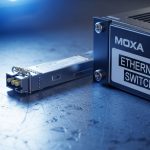
EtherNet IP SFP: How fiber SFP behaves in an industrial EtherNet/IP link

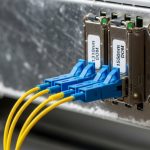
EtherNet/IP over fiber typically uses standard Ethernet physical-layer behavior, but the operational goal is different: deterministic connectivity between control logic (PLC, safety controller, motion controller) and the rest of the plant network. An EtherNet IP SFP is the physical media interface—your switch or media converter hosts the SFP cage, while the SFP module provides the optical transmitter/receiver, link negotiation, and diagnostics. In practice, many “EtherNet/IP problems” are actually optical layer issues: receive power too low, wrong fiber type, connector contamination, or DOM mismatches that the switch interprets as unsafe.
What engineers actually watch during commissioning
During cutover, you generally validate three layers at once: optical link budget, Ethernet link state, and application behavior. On the optical side, you measure receive power (often in dBm) at the far end or rely on switch DOM readings, then confirm the link stays up under vibration and temperature swings. On the Ethernet side, you confirm the switch port shows the expected speed/duplex and no excessive CRC/frame errors. On the control side, you correlate link events with PLC communication tags and fault history.
For EtherNet/IP networks, physical-layer compliance matters because the Ethernet standard drives what “good” looks like for framing and electrical/optical signaling. IEEE 802.3 defines the Ethernet physical requirements and link behavior across media types. A useful reference starting point is IEEE 802.3 Ethernet Standard.
Fiber reach and wavelength: Comparing common EtherNet IP SFP optics (SR vs LR)
Not all fiber SFPs are interchangeable, even when they share the same nominal speed. The biggest differentiator is the optical profile: wavelength, reach, and fiber type (multimode versus single-mode). In day-to-day plant work, “wrong optics” is the most frequent root cause when a new rack or line extension fails to link.
Typical fiber SFP categories you will see in Rockwell environments
In industrial designs, you most often encounter 1G SFP and 10G SFP variants, plus a growing number of higher-speed modules depending on the plant backbone. The classic multimode short-reach family uses 850 nm (often labeled SR). Single-mode long-reach uses 1310 nm (often labeled LR). Some vendors also offer extended reach using 1550 nm, but those appear more in campus and aggregation segments.
Technical specifications comparison table
Use this table as a quick mental model for what to verify on the datasheet label and what your switch will expect. Always confirm the exact model number and DOM behavior from the vendor datasheet before deploying.
| Optical type | Wavelength | Typical reach (MM/SM) | Connector | Data rate | Tx/Rx power class (typ.) | Operating temperature | DOM |
|---|---|---|---|---|---|---|---|
| 10G SR (MM) | 850 nm | Up to 300 m on OM3/OM4 MM | LC | 10G Ethernet | Low-mW class (varies by vendor) | -40 C to +85 C (common) | Yes (vendor-specific) |
| 10G LR (SM) | 1310 nm | Up to 10 km on SMF | LC | 10G Ethernet | Higher power class (varies) | -40 C to +85 C (common) | Yes (vendor-specific) |
| 1G SX (MM) | 850 nm | Up to 550 m on OM2 (legacy) | LC | 1G Ethernet | Low-mW class (varies) | -40 C to +85 C (common) | Yes/No (depends) |
| 1G LX (SM) | 1310 nm | Up to 10 km on SMF | LC | 1G Ethernet | Low-mW class (varies) | -40 C to +85 C (common) | Yes/No (depends) |
Real vendor examples you can validate against
In the field, you will see modules like Cisco SFP-10G-SR and Finisar FTLX8571D3BCL (examples of SR-class optics), as well as FS.com SFP-10GSR-85 for cost-conscious spares. The exact compatibility depends on your switch model and whether the port firmware expects specific DOM formatting or vendor IDs. Always cross-check the vendor datasheet and your switch’s transceiver compatibility list.
For general fiber and optical planning, the Fiber Optic Association provides practical fundamentals that complement datasheets. A helpful reference is Fiber Optic Association.
Head-to-head: Compatibility with Allen-Bradley and Rockwell switches and controllers
Compatibility is where engineering time disappears: an SFP that works in one switch may fail or rate-limit in another. The key is that Rockwell environments depend on predictable port behavior, and transceiver modules can influence port status through DOM, vendor ID fields, and sometimes EEPROM layout. Some industrial switches enforce stricter “known-good” transceiver lists, while others accept a broader range of standards-compliant modules.
What to check before you order
Start with the exact switch and port type (for example, managed managed industrial Ethernet switches that host SFP or SFP+ cages). Then verify: supported link speeds for that port, whether the port is configured for auto-negotiation or forced speed, and whether the switch requires DOM presence. In many deployments, engineers also standardize on one vendor family for optics and keep identical modules in spares to reduce variance during replacement.
DOM, EEPROM, and the “it links but behaves wrong” scenario
DOM (Digital Optical Monitoring) is typically implemented over a standard serial interface and exposes thresholds and current readings. If your switch firmware reads DOM and detects an out-of-range value, it may log errors or administratively disable the port. Even when the link LEDs look “up,” the port counters can reveal hidden degradation such as rising bit error rates. This is why you should validate not just link state but also error counters after installation.
Pro Tip: In industrial plants, the most misleading symptom is “link up, but PLC I/O is intermittent.” Before you suspect controller logic, pull port counters for CRC, FCS, and alignment errors, then compare DOM receive power against the module vendor’s minimum sensitivity. A marginal optical path can pass link negotiation while still producing enough physical-layer errors to disrupt EtherNet/IP traffic patterns.
For EtherNet/IP design constraints related to industrial network performance, it is also useful to reference how industrial Ethernet profiles map to standard Ethernet behavior. ITU documentation can help frame general network performance considerations, and while it does not replace vendor datasheets, it supports your overall requirements thinking via ITU.
Decision matrix: Cost, optics, and operational risk in EtherNet IP SFP selection
Choosing an EtherNet IP SFP is a trade between optics performance, deployment speed, and the operational risk of field failures. OEM modules can reduce compatibility uncertainty, while third-party modules can dramatically reduce upfront cost—if you validate DOM behavior and power classes with your specific switch firmware. The best outcome usually comes from selecting the correct optical profile first (SR/SX versus LR/LX), then controlling the compatibility variables.
Ordered selection criteria checklist engineers use
- Distance and fiber type: Determine MM versus SM, and confirm OM3/OM4 versus legacy OM2, then match wavelength class (850 nm SR/SX or 1310 nm LR/LX).
- Data rate and port capability: Confirm the port supports the module’s exact speed (1G versus 10G) and whether it uses SFP or SFP+ cages.
- Switch compatibility: Check the switch model’s transceiver compatibility guidance and firmware behavior for DOM.
- DOM support and thresholds: Verify the module provides DOM and that the switch recognizes it without disabling the port.
- Operating temperature: In cabinets, confirm the module spec supports the ambient conditions (often -40 C to +85 C, but measure your cabinet rise).
- Budget and spares strategy: Compare OEM cost versus third-party cost, but plan for consistent spares to reduce variance during swaps.
- Vendor lock-in risk: If you standardize on one OEM family, assess long-term sourcing and price volatility for future expansions.
Cost and ROI note: what the numbers look like in the real world
Street pricing varies by speed and reach, but a realistic range for typical fiber SFP modules often lands around $40 to $200 for many 1G/10G fiber optics, depending on OEM versus third-party and whether you need extended temperature grades. Total cost of ownership (TCO) is shaped less by purchase price and more by downtime risk, spare inventory handling, and the time spent validating compatibility. In a plant with dozens of spares, standardizing one vetted module family can lower commissioning time and reduce the probability of repeat truck rolls.
Field experience also shows failure rates correlate with handling: bent fiber, dirty LC end faces, and ESD during module insertion can cause premature degradation. So the ROI often comes from pairing the right module with correct fiber hygiene practices and clear maintenance intervals, not from chasing the lowest unit price.
Decision matrix table
| Option | Best for | Compatibility risk | Optical performance confidence | Upfront cost | Operational TCO |
|---|---|---|---|---|---|
| OEM-aligned SFP (known-good) | Critical control segments, strict switch firmware | Low | High | Higher | Often lowest when downtime is expensive |
| Third-party SFP (validated) | Expansion projects with testing window | Medium (if not validated) | Medium to high | Lower | Good if you enforce DOM and link budget checks |
| Mixed vendor spares | Short-term emergency replacement | High | Variable | Unpredictable | Usually higher due to troubleshooting time |
Common pitfalls and troubleshooting tips for EtherNet IP SFP links
Below are the issues that most often show up when an EtherNet/IP segment goes unstable after a transceiver change. Each entry includes a likely root cause and a practical fix you can apply during maintenance windows.
Link flaps only under load
Root cause: Optical budget is marginal: fiber attenuation is higher than expected, or connector contamination is intermittent. Even if the link negotiates, error counters can spike under higher traffic bursts.
Solution: Clean LC connectors, inspect end faces with a microscope, then verify receive power (DOM) against the vendor’s minimum sensitivity. If the receive power is close to the threshold, shorten the patch path or replace the fiber run with correct grade (OM3/OM4 for SR).
Port stays down after insertion, or switch logs transceiver errors
Root cause: DOM compatibility or transceiver type mismatch. Some switches reject modules that do not match expected EEPROM formatting or required optical class fields.
Solution: Confirm you installed the correct wavelength class and speed variant (for example, 10G SR versus 10G LR). Then try a known-good OEM module to isolate whether the port firmware is rejecting the third-party EEPROM/DOM data.
“Works on my bench” but fails in the cabinet
Root cause: Temperature or airflow assumptions are wrong. A module rated for -40 C to +85 C may still fail earlier if the cabinet ambient is higher than expected or if there is poor convection around the cage.
Solution: Measure cabinet ambient temperature near the switch and SFP cages during peak operation. If needed, adjust airflow, add cabinet fans, or choose industrial-grade modules with verified operating temperature margins.
Wrong fiber type: MM installed where SM is required
Root cause: Confusing OM and OS labeling, or reusing a cable plant that does not match the planned optics. SR modules on the wrong fiber can appear to work briefly, then degrade quickly.
Solution: Verify fiber type at the patch panel using test records and fiber certification documentation. Then match connectorization and wavelength to the actual fiber grade: SR/SX with OM MM, LR/LX with SMF.
Which Option Should You Choose?
If you are deploying new EtherNet/IP fiber segments for Allen-Bradley and Rockwell systems and you cannot afford validation delays, choose OEM-aligned SFP modules that are explicitly compatible with your switch model and that provide DOM readings your firmware accepts. If you are expanding a mature plant and you have a controlled testing window, choose third-party SFP modules that you validate end-to-end with your exact port firmware, error counters, and optical receive power targets. Avoid mixed vendor spares for critical control links unless you have confirmed identical DOM behavior and stable port counters across swaps.
Next, map your plant’s fiber plant and port list to the exact optics plan—then review related transceiver topics using EtherNet IP SFP compatibility, DOM diagnostics for fiber transceivers, and 10G SR vs LR fiber planning.
FAQ
What makes an SFP “EtherNet IP SFP” versus a normal Ethernet SFP?
In most cases, the module is a standard Ethernet physical-layer SFP; the “EtherNet/IP” label refers to how it is used within an EtherNet/IP network. Compatibility depends on your switch and firmware expectations for speed, DOM, and diagnostics. Always verify the module works on your specific Rockwell switch ports and maintains stable error counters.
Can I use 10G SR and 10G LR modules interchangeably?
No. SR and LR use different wavelengths and are designed for different fiber types and distances. If you mismatch wavelength class and fiber type, you may see link failures or unstable links due to insufficient receive power and higher error rates.
Do I need DOM support for Rockwell-managed switches?
DOM is strongly recommended because many industrial switches use DOM readings for monitoring, threshold alarms, and sometimes port protection behavior. If DOM is missing or formatted differently, the switch may log errors or disable the port depending on firmware policy.
What is the fastest way to troubleshoot an EtherNet/IP SFP link issue?
Start with physical checks: clean LC connectors, inspect end faces, and confirm the correct fiber grade (MM versus SM). Then verify port counters and DOM receive power; a marginal optical path can present as intermittent EtherNet/IP traffic even when link LEDs appear normal.
How do I reduce downtime during SFP swaps in a production line?
Standardize your spares: keep identical part numbers and optical classes, and pre-label patch cords by wavelength and fiber type. Also perform a quick post-swap validation: verify link stability and check CRC/FCS error counters for several minutes under typical traffic.
Are third-party EtherNet IP SFP modules safe for mission-critical control?
They can be safe if they are validated with your exact switch model, including DOM behavior and optical budget under real temperatures. If you cannot validate, OEM-aligned modules are usually the lower operational risk for mission-critical segments.
Author bio: I design resilient industrial network interfaces and transceiver validation workflows from the perspective of hands-on field commissioning. I focus on optical link budgets, DOM-driven monitoring, and operator-friendly diagnostics so control networks stay stable under real plant conditions.