If your data centers are getting denser and power budgets are tightening, optical module choice becomes a deployment risk, not just a procurement line item. This article helps network engineers and field technicians select, validate, and troubleshoot high-density transceivers using real-world distance, temperature, and switch-compatibility constraints. You will also get a deployment checklist, common failure modes, and an engineer-focused ROI view.
Start with the link map: budget distance, not just “reach”

In data centers, the fastest way to get burned is to buy a “supported reach” module without building an optical link budget that matches your actual plant. I typically begin every deployment by mapping rack-to-rack fiber runs, patch panel loss, and any MPO/MTP fanout components before I even open a transceiver datasheet.
For example, a 10 km “reach” spec is usually measured under controlled launch conditions with a defined reference optical power and receiver sensitivity. Your real system adds connector insertion loss, splice loss, and sometimes extra patching cycles that quietly consume the margin. If you are using OM4 or OS2, also verify that the installed fiber type and modal bandwidth (for multimode) match the module’s assumed fiber characteristics.
Practical steps I use on-site
- Collect fiber plant data: fiber type (OM3/OM4/OS2), core size, and measured insertion loss per trunk and patch path.
- Include passive components: MPO/MTP fanouts, trays, and any additional patch panels.
- Translate to link budget: compare your estimated received power to the module’s receiver sensitivity and allowable power range.
- Validate polarity and lane mapping for MPO: polarity errors can look like “bad optics,” but the optics are fine.
Reference the Ethernet physical-layer expectations for optical links and link behavior in IEEE 802.3 Ethernet Standard.
- Best-fit scenario: Any mixed plant where you have variable patching and multiple fanout points.
- Pros: Prevents overspend on “long reach” parts and avoids surprise link failures.
- Cons: Requires plant documentation or field measurements.
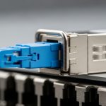
Choose the highest-density form factor that your switches can truly run
High-density deployment in data centers is often limited by more than optics. Switch ASIC port grouping, lane mapping, and supported module types define what “works” in practice, especially at 25G and above. I have seen teams order a perfect transceiver spec sheet, only to discover the switch requires a specific vendor-coded EEPROM profile or only supports certain temperature grades.
In day-to-day work, I treat form factor selection as a compatibility project. Common high-density options include SFP28 (typically lower density), QSFP+ for 40G, QSFP28 for 100G, and QSFP-DD or OSFP for higher density 200G and 400G. The key is to verify that your switch model supports that exact module family and data rate, and that it supports the specific optical technology (SR, LR, ER, DR, FR).
For example, in a 1U switch with 32 or 48 ports, you might be tempted by QSFP-DD for 400G breakout or 200G modes. But the switch may only support a subset of breakout patterns, and some ports share a common SerDes block. Always check the switch transceiver compatibility matrix in the vendor guide and confirm the supported “breakout mode” for your exact module type.
- Best-fit scenario: New deployments where you control both switch selection and module ordering.
- Pros: Maximizes port density and reduces rack space cost per Tbps.
- Cons: Compatibility constraints can force a narrower module set.
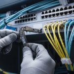
Multimode SR for short reach: deploy OM4 carefully with power margin discipline
Short-reach links are where multimode optics shine, especially in data centers with structured cabling and predictable rack-to-row runs. 10GBASE-SR and 25G/50G/100G SR variants are widely supported, and multimode reduces cost per link compared to long-reach single-mode optics. The tradeoff is that multimode performance depends heavily on fiber type, cleaning quality, and patching count.
In operational terms, I treat multimode SR as a “quality management” project. If you have frequent moves, adds, and changes, the number of connector cycles and cleaning laps can cause intermittent failures. With MPO/MTP trunks, lane skew and polarity errors can also masquerade as receiver power issues.
For 100G over multimode, you will often see 850 nm VCSEL-based SR modules designed for OM4. A representative example is Finisar FTLX8571D3BCL (100GBASE-SR4 class) used in many deployments, but you must confirm the switch’s matrix and your fiber plant’s modal bandwidth.
| Spec Item | Typical Multimode SR (Example: 100GBASE-SR4) | Typical Single-mode LR (Example: 100GBASE-LR4) |
|---|---|---|
| Wavelength | ~850 nm | ~1310 nm |
| Fiber Type | OM4 (often required) | OS2 single-mode |
| Reach (order-of-magnitude) | ~100 m to 150 m (depends on spec) | ~10 km (depends on class) |
| Connector / Interface | MPO-12 (commonly) | LC or MPO (varies) |
| Power / Sensitivity | Budget depends on patching and cleaning | More margin with fewer modal effects |
| Operating temp | Verify switch and module grade (often commercial vs industrial) | |
| Best use | In-rack and intra-row links | Inter-row, aggregation, and longer runs |
- Best-fit scenario: Data centers with OM4 backbone and short patch runs, where you can enforce cleaning and polarity checks.
- Pros: Lower cost and excellent performance for short distances.
- Cons: Sensitive to fiber quality and connector handling.
Single-mode LR/DR for row-to-row: reduce operational variability
Single-mode optics are a practical answer when your data centers have inconsistent patching, longer runs, or a plant that cannot be guaranteed to OM4-grade multimode cleanliness. LR and DR modules use narrow-beam propagation, which makes them more tolerant of patch panel variations and modal dispersion concerns that plague multimode.
In a field deployment, this tolerance often converts directly into fewer truck rolls. For instance, if you are connecting 48-port ToR switches to aggregation in a leaf-spine topology with patch-heavy reconfiguration, using single-mode with LC connectors can reduce the probability of intermittent link faults caused by connector cycles.
As an example of common product families for 10G single-mode, Cisco SFP-10G-SR is multimode (not single-mode), but you would typically choose a 10GBASE-LR/LRM-class single-mode module for longer runs. On the 100G side, QSFP28 LR4 modules are widely used; always confirm whether your switch expects a specific DOM behavior and whether it enforces transmitter power limits tightly.
ITU guidance on optical fiber and cabling practices can help at the standards level: ITU-T Recommendations and standards portal.
- Best-fit scenario: Inter-row links, data halls with long backbone runs, and environments with frequent re-cabling.
- Pros: More robust operationally; often fewer intermittent errors.
- Cons: Higher module cost and requires OS2 plant.
DOM and diagnostics: treat it as an engineering signal, not a feature
Modern optical modules expose digital optical monitoring (DOM) parameters such as received power (Rx power), transmitted power (Tx power), laser bias current, and temperature. In data centers, DOM is crucial for early failure prediction and for controlling link stability during high-density changes.
However, DOM behavior is not perfectly uniform across vendors and module grades. Some third-party modules report values with different scaling or update intervals, and some switches enforce thresholds that can trigger warnings or even port disable events if the reported readings fall outside expected ranges. For that reason, I validate DOM behavior during commissioning by comparing readings against a known-good baseline module in the same switch and port group.
During burn-in, I log DOM every minute for the first 24 to 48 hours and correlate it with interface error counters (FEC corrected/uncorrected errors for modern optics) and with environmental sensor changes (inlet temperature and airflow changes). If you use SNMP or telemetry, ensure your sampling interval is not so slow that you miss fast transients.
- Best-fit scenario: Networks with strict availability targets, proactive monitoring, and frequent module swaps.
- Pros: Enables predictive maintenance and faster root cause analysis.
- Cons: Compatibility differences can cause threshold mismatches.
Power, thermal, and airflow: the hidden limiter in dense racks
High-density optical deployments in data centers can fail because of thermals, not because of optical budget. Transceivers dissipate power at both steady state and during initialization, and the thermal profile depends on cage design, airflow direction, and the presence of blanking panels. A module that is “within spec” in a lab can still overheat in a real rack with blocked intake vents.
On-site, I check inlet temperature at the switch and measure airflow patterns using a handheld anemometer or smoke visualization (carefully and safely). I also verify that the switch port side has unobstructed ventilation and that cable bend radii do not block airflow. Many platforms specify an operating temperature range that must include worst-case conditions at the module cage, not just the room thermostat.
From an engineering perspective, treat thermal margin like optical margin: it is finite. If you are deploying 400G-class optics, the module power and heat flux can be significantly higher than older generations, which makes correct airflow management and cable management non-negotiable.
- Best-fit scenario: Hot-aisle/cold-aisle optimization projects and high-capacity spine or leaf switches.
- Pros: Prevents “mysterious” link flaps under load.
- Cons: Requires rack-level mechanical checks and measurement time.
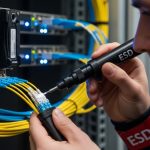
Build a compatibility lab workflow: validate before you scale
Engineers often assume that “IEEE-compliant optics” automatically work across vendors. In practice, compatibility is influenced by vendor-specific EEPROM fields, vendor-defined thresholding, and switch firmware expectations. For high-density data centers, the cost of a slow validation cycle is usually cheaper than the cost of a large-scale outage caused by a subtle incompatibility.
My workflow is simple and repeatable. I select one switch model and one port group that represents the densest deployment, then test the exact module SKU you plan to use. I run link bring-up checks, then stress the link with sustained traffic and monitor error counters and DOM readings for 24 hours.
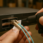
If you have strict requirements, also test optical cleanliness handling. Use a controlled cleaning process (lint-free wipes and approved alcohol, plus fiber inspection) before connecting. Many “compatibility” failures are actually contaminated connectors that reduce optical power enough to cause retries and link instability.
For standards-level and ecosystem context around optical interfaces and interoperability, Fiber Optic Association is a practical reference for field-safe handling and inspection concepts.
- Best-fit scenario: Multi-site rollouts where you need consistent behavior across identical switch families.
- Pros: Reduces risk and speeds commissioning.
- Cons: Requires time and a controlled test environment.
ROI and cost control: balance OEM support with third-party economics
When you deploy high-density optics at scale, cost per module matters, but total cost of ownership (TCO) matters more. OEM optics may be pricier, yet they can reduce commissioning time, lower the risk of incompatibility, and provide predictable warranty pathways. Third-party optics can cut upfront cost, but you must factor in validation labor, potential firmware quirks, and higher replacement rates if you do not enforce strict handling and cleaning.
In many data center programs, 10G and 25G optics fall into the “commodity-like” category with a smaller performance gap across reputable vendors. For 100G and above, the BOM impact and the operational risk rise because the physical layer is more complex and the module is more sensitive to thermal and power constraints. As a rule, I treat budget optics as acceptable only when the compatibility matrix is confirmed and the DOM thresholds behave within expected ranges.
Realistic price ranges vary by contract and volume, but a field-friendly planning model could look like: OEM 10G SR modules often cost roughly in the tens to low hundreds USD per unit, while 100G SR and QSFP28-class optics can be multiples of that; 400G-class optics can be significantly higher. Your TCO should include: module cost, installation labor, test bench time, expected failure rate, and the cost of downtime during swaps. Also consider that power savings from higher-efficiency optics can matter at scale, but only if your cooling plan is already correct.
- Best-fit scenario: Budget-constrained deployments where you still require predictable commissioning.
- Pros: Optimizes spend without sacrificing reliability targets.
- Cons: Requires governance for vendor selection and validation.
Common mistakes / troubleshooting in high-density data center optics
Below are failure modes I have personally seen during commissioning and field maintenance. Each item includes a root cause and a practical fix.
“It should work” assumptions about switch compatibility
Root cause: The module is electrically compatible but not fully compatible with the switch’s EEPROM parsing, DOM thresholds, or supported breakout mode. Some platforms also enforce vendor-specific laser safety and power limit behaviors.
Solution: Validate the exact module SKU in the exact switch and port group. Use the switch’s compatibility matrix and confirm the breakout mode (for example, 100G to 4x25G) if you are using breakout-capable optics.
MPO polarity and lane mapping errors
Root cause: MPO polarity misconfiguration or reversed lane mapping can produce consistent link failures or high error rates. This often looks like “bad optics” even though the transceiver is fine.
Solution: Verify polarity using an MPO polarity method (A/B) consistent with your patching scheme, and confirm lane mapping during installation. If errors persist, swap the MPO polarity adapters and re-check link status and Rx power per lane where the platform exposes it.
Dirty connectors leading to power starvation and intermittent link flaps
Root cause: Contamination on LC or MPO endfaces reduces transmitted power and increases return loss. In high-density data centers, repeated insertions during maintenance worsen the issue.
Solution: Enforce a cleaning and inspection workflow: inspect with a fiber scope, clean using approved methods, then reconnect. After cleaning, re-check DOM Rx power and interface error counters. Replace damaged ferrules or cracked endfaces—cleaning will not fix mechanical damage.
Thermal throttling and airflow blockage
Root cause: Heated air recirculation near the module cage increases module temperature beyond safe operating margin, causing link drops under load.
Solution: Validate inlet temperature and airflow path. Remove obstructions, confirm blank panels are installed, and ensure cables are routed without blocking vents. Re-test under sustained traffic and monitor module temperature via DOM.
Ignoring DOM behavior differences across vendors
Root cause: Some modules report DOM values differently or update at different intervals, which can trigger switch alarms or cause threshold mismatches.
Solution: During commissioning, baseline DOM readings with a known-good module, then compare the third-party module under identical conditions. If the switch enforces strict thresholds, adjust your alarm thresholds only if your operations policy allows it.
Pro Tip: During commissioning, log received power and interface error counters together for at least 24 hours. Many teams watch link up/down status, but the real early warning is a slow Rx power drift paired with rising corrected-error counts.
FAQ for engineers deploying optical modules in data centers
Which optical type is safest for dense data centers with frequent moves?
For environments with frequent re-cabling, single-mode LR/DR optics are often operationally safer than multimode SR because single-mode is less sensitive to modal dispersion and certain patching variations. That said, cleanliness and polarity discipline still matter. If your plant is OM4 and you can enforce cleaning, multimode SR can be cost-effective.
How do I confirm switch compatibility beyond “the module fits the port”?
Check the switch vendor’s transceiver compatibility matrix for the exact module SKU and supported data rate mode. Then validate in a lab or staging rack by running traffic and monitoring DOM and error counters. This avoids surprises caused by EEPROM parsing differences and port group SerDes sharing.
What DOM metrics should I watch first during commissioning?
Start with module temperature, laser bias current, and Rx optical power. Then correlate those with interface-level error counters (including corrected vs uncorrected errors where supported). If you see power drift or temperature spikes, investigate airflow and optical cleanliness before assuming a hardware defect.
Are third-party optics acceptable in data centers?
Yes, but only with governance: verify compatibility, validate DOM behavior, and enforce cleaning and inspection standards. Many failures attributed to “bad optics” are actually connector contamination or polarity mistakes. Use a controlled pilot deployment before scaling across sites.
What is the most common cause of “link flaps” in high-density racks?
In my experience, the top causes are dirty connectors, thermal airflow issues, and polarity errors. Link flaps that correlate with traffic load often point to thermal or power/laser bias behavior. Link flaps that correlate with maintenance events often point to cleaning and insertion quality.
How should I plan ROI when upgrading to higher-density optics?
Include TCO: module cost, commissioning labor, expected failure rate, and downtime cost for swaps. Higher-density optics can reduce rack space and cabling cost, but they also increase thermal sensitivity and commissioning complexity. Model power and cooling implications alongside optics cost to avoid underestimating infrastructure upgrades.
High-density optical deployments in data centers succeed when you treat optics selection as an end-to-end engineering workflow: link budget, compatibility validation, thermal management, and disciplined handling. If you want to go deeper on operational governance, see fiber cleaning best practices and DOM monitoring workflows for field-ready procedures.
| Rank | Top pick | Best for | Why it ranks high |
|---|---|---|---|
| 1 | Link map and budget distance | All deployments | Prevents overspec and avoids optical margin failures |
| 2 | Form factor aligned to switch capability | High-density rollouts | Reduces compatibility risk and port-group surprises |
| 3 | DOM-first commissioning and monitoring | Operations teams | Enables early warning and faster root cause |
| 4 | Thermal and airflow verification | Dense racks and 100G+ optics | Prevents load-triggered flaps and overheating |
| 5 | Single-mode LR/DR for variability tolerance | Patch-heavy environments | More robust to plant inconsistencies than multimode |
| 6 | Multimode SR with OM4 discipline | Short reach with stable handling | Lower cost with strong performance when clean |
| 7 | Compatibility lab workflow | Multi-site scaling | Reduces large rollout risk via staging validation |
| 8 | ROI and vendor strategy governance | Budget-constrained programs | Balances cost and risk with realistic TCO accounting |
Author bio: I am a field-focused photographer and technical writer who documents network hardware commissioning from the rack side, including optical cleaning, DOM logging, and thermal verification. I have worked with engineers deploying 10G to 400G optical links in operational data centers under real constraints.