In dense server and switching racks, SFP module failures often look random: link flaps, CRC errors, or “unsupported transceiver” alarms. This article lays out field-tested best practices for deploying SFP modules in high-density environments so you can reduce downtime and prevent silent performance loss. It is written for network engineers, data center field technicians, and operations teams who must verify optics, power, and compatibility before and after install. It also includes concrete specs, a decision checklist, and troubleshooting scenarios you can apply during change windows.
Top 7 best practices: choose the right SFP class and optics
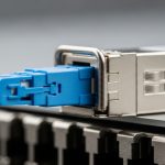
Most “it should work” outages come from selecting the wrong SFP family for the physical layer and reach. In practice, you must match the transceiver type (for example, SFP vs SFP+ vs SFP28) and the optical standard (SR for multimode short reach vs LR/ER for single-mode). IEEE Ethernet links rely on physical coding and lane behavior that may differ across generations, so the switch port and optics must align. For standards context, review the Ethernet physical layer baseline in IEEE 802.3 Ethernet Standard.
What to verify before you order
Start with the switch or NIC port capability, including nominal data rate and supported optical ranges. For example, a 10G SFP+ port typically expects 10.3125 Gbps line rate for 10G Ethernet, while a 25G SFP28 port expects 25.78125 Gbps line rate. Next, confirm the fiber type: multimode (OM3/OM4) for SR modules, or single-mode (OS2) for LR/ER modules. Finally, confirm connector style: common variants include LC for most modern deployments and older SC in legacy buildings.
Best-fit scenario
In a high-density colocation row with 42U cabinets holding 10G and 25G top-of-rack switches, operators often mix SR optics for leaf-spine links inside the same row. If you standardize on OM4 for all short runs, you can use 10G SR and 25G SR modules across many ports, reducing inventory complexity. The key is to ensure every chassis model and port profile is compatible with the chosen SFP generation.
- Pros: Fewer “link down” events; less inventory sprawl; easier staging.
- Cons: Requires disciplined port mapping and labeling before install.

Top 7 best practices: run optical budget checks and cleanliness controls
In high-density deployments, optical budget failures rarely show up as “no link” immediately. Instead, you may see intermittent CRC errors, rising BER, or link renegotiation under temperature swings. Best practices require both optical power budgeting and strict fiber end-face cleanliness controls. Even when the module is “within spec,” contamination on LC connectors can cause fast degradation, especially in frequently handled patch panels.
Optical budget math engineers actually use
For SR and short-reach multimode links, you must consider: transmitter launch power, receiver sensitivity, fiber attenuation, connector loss, splice loss, and any patch cord mated loss. For single-mode LR/ER, the same approach applies, but dispersion and wavelength stability become more critical. Use vendor datasheets for sensitivity and launch power, then add a conservative margin (many teams target an extra 3 dB to 6 dB over the calculated loss for aging and handling). Cleanliness and insertion loss variance often dominate in field conditions.
Cleanliness workflow
Adopt a consistent routine: inspect connector end faces with a scope, clean with validated wipes or swabs, and re-inspect before mating. In dense racks, connectors are repeatedly bumped during cable management, so you should treat every “re-seat” as a potential contamination event. If you use factory-terminated patch cords, still inspect end faces after installation.
Best-fit scenario
In a 3-tier data center leaf-spine topology with 48-port 10G ToR switches and densely packed patch panels, a single contaminated LC pair can affect multiple uplinks during maintenance. Teams that enforce an “inspect-clean-mate” rule typically reduce repeat truck rolls for intermittent errors. During acceptance testing, they also log link error counters after a 30-minute warm-up period, catching marginal optical conditions before the window closes.
- Pros: Prevents silent degradation; improves link stability after moves.
- Cons: Requires connector inspection tools and process discipline.

Top 7 best practices: match SFP electrical features, DOM, and switch policies
Modern switches frequently enforce transceiver policies using digital optical monitoring (DOM) and vendor-defined thresholds. If the module is slightly out of range due to aging or temperature, the switch may log warnings or even disable the port depending on configuration. Best practices include validating DOM support, confirming alarm behavior, and aligning physical layer expectations with the platform.
DOM and alarm thresholds
DOM typically provides real-time metrics such as transmitted optical power, received optical power, bias current, module temperature, and sometimes supply voltage. Your operational best practice is to establish a baseline during commissioning: record DOM readings at steady state and after a controlled thermal cycle if the facility permits. Then set alert thresholds that catch drift early without causing nuisance alarms.
Compatibility caveats that matter
Not all third-party modules implement DOM identically, and some platforms perform strict checks on vendor identifiers. Even when a module meets the optical spec, a strict “vendor ID allowlist” can block activation. If you must use third-party optics, validate on the exact switch model and software version you run today, not just the hardware generation.
Best-fit scenario
In a campus core with mixed switch generations, operations teams often standardize on one optics vendor for the first year, then evaluate third-party replacements module-by-module. During that phase, they compare DOM telemetry stability across 20 to 30 ports and confirm that alarms do not trigger during normal airflow changes. This approach minimizes surprises when you later scale the deployment to adjacent racks.
- Pros: Predictable alerting; fewer “unsupported optics” events.
- Cons: Vendor lock-in risk; extra validation workload.

Top 7 best practices: stage, test, and burn in before you rack
High-density environments punish “ship and pray” behavior. A best practice is to stage modules in a controlled test area and validate link performance before they ever enter a live cabinet. This reduces change-window risk and prevents you from spending the first hour of an outage diagnosing a module that was never electrically verified. It also helps you separate optics defects from fiber path issues.
Field-ready test plan
At minimum, test each module in its target port type and configuration. If your switch supports it, verify DOM readings and confirm that link is stable at line rate for a defined period. A common operational pattern is: connect, verify link up, run traffic for 15 to 30 minutes, then check interface counters for CRC, FEC (if applicable), and symbol errors. If you support it, perform a longer burn-in for a subset (for example, 2 to 5 modules per lot) to catch early failures.
Selection of test optics and traffic
Use the actual fiber patch cords and jumper lengths you intend to deploy, not lab-grade equivalents with shorter runs. Drive representative traffic patterns for your environment: for example, bidirectional flows with typical packet sizes and sustained throughput. In storage networks, you may need to validate microbursts and pause-frame behavior; in general Ethernet environments, watch for sustained error counters and link renegotiation events.
- Pros: Faster troubleshooting; fewer dead-on-arrival failures.
- Cons: Requires staging space and time; adds operational overhead.
Top 7 best practices: use a disciplined labeling and change-control system
In dense racks, the physical mapping between ports, fibers, and modules is a primary source of errors. Best practices treat labeling as a safety feature: it prevents swapping SR and LR optics, mispatching LC pairs, and confusing “works in test” with “works in production.” A robust system also accelerates rollback during incidents because engineers can identify the exact optic and fiber path involved.
Labeling that survives real operations
Label both ends of each fiber run and each transceiver location. Use a consistent naming convention tied to rack, switch, and port number. Include the transceiver type (for example, “10G-SR-OM4-LC”) and the expected reach class. During change control, record the exact module part number and serial number, plus the DOM baseline readings at deployment time.
Best-fit scenario
In a high-density migration where 200+ ports are moved between two rows, teams that use end-to-end labeling and a pre-printed port mapping sheet typically cut rollback time from hours to minutes. They also reduce “wrong patch cord” incidents by verifying patch cord polarity and connector mating before energizing traffic. When you later audit, you can correlate failure clusters to specific lots or specific racks.
- Pros: Lower human error; faster restoration.
- Cons: Requires process adoption and periodic audits.
Top 7 best practices: compare module types and verify key specs before deployment
Engineers need a quick way to compare optics options that meet the same functional goal. Below is a practical comparison table for common SFP-family optics used in high-density environments. Use it to sanity-check wavelength, reach class, connector type, and operating temperature before you commit to an install plan.
| Module type (example) | Typical data rate | Wavelength | Reach class (typical) | Fiber type | Connector | Power/Temp notes |
|---|---|---|---|---|---|---|
| SFP-10G SR (e.g., Cisco SFP-10G-SR) | 10G Ethernet | ~850 nm | ~300 m on OM3, ~400 m on OM4 | Multimode OM3/OM4 | LC | Low power; temperature typically commercial (about 0 C to 70 C) |
| SFP+ 10G LR (single-mode) | 10G Ethernet | ~1310 nm | ~10 km typical | Single-mode OS2 | LC | Higher link budget; validate OS2 attenuation and splices |
| SFP28 25G SR (example) | 25G Ethernet | ~850 nm | ~100 m on OM3, ~150 m on OM4 (varies) | Multimode OM3/OM4 | LC | More sensitive to loss; cleanliness matters more at higher rates |
| Third-party SFP modules with DOM | Varies | Varies by standard | Varies | Varies | Varies | Confirm DOM telemetry behavior and switch policy compatibility |
Best-fit scenario
In a modern high-density switch fabric where you mix short-reach and longer-reach uplinks, you can standardize multimode SR for intra-row links and single-mode LR for inter-row links. For example, keep OM4 patching for up to 400 m and reserve OS2 LR for anything beyond that. This reduces optical budget complexity and keeps spares more uniform.
- Pros: Faster procurement and fewer mismatched orders.
- Cons: Datasheet reach is not a guarantee; budget still depends on your losses.
Top 7 best practices: balance cost, spares, and operational risk
Cost decisions in optics are rarely just the purchase price. Best practices include total cost of ownership: failure rates, downtime cost, spare strategy, and power/thermal implications. In many facilities, the cost of an extra truck roll or a prolonged incident dwarfs the difference between OEM and third-party optics.
Realistic price and TCO perspective
As a planning baseline, many 10G SR SFP/SFP+ modules often fall into a broad price band depending on OEM, vendor, and warranty. In practice, OEM modules can be materially higher, while third-party modules may be cheaper but can increase compatibility validation and return friction. Consider stocking spares by reach class and wavelength, not just by speed; and keep enough spares to cover peak failure periods during migrations.
Operational ROI approach
Compute ROI using downtime impact: estimate incident time-to-repair, labor cost, and business impact for each port. Then compare OEM vs third-party with your measured failure behavior from prior deployments. Teams that run a disciplined acceptance test and baseline DOM telemetry typically get better reliability out of either category, because they filter out marginal lots earlier.
- Pros: Better budgeting; fewer hidden costs from incompatibility.
- Cons: Requires tracking incident outcomes and inventory performance.
Common mistakes and troubleshooting tips for SFP deployments
Even with careful planning, failures happen. Below are concrete pitfalls commonly seen in high-density environments, with root causes and practical fixes. These are written as best practices to prevent repeat incidents, not as a substitute for vendor support.
Mistake: mixing SR and LR optics on similar-looking ports
Root cause: A swapped transceiver type can still “show link” in some cases, but with unstable performance or immediate errors due to wavelength and fiber mismatch. This is especially common when cabinets are labeled inconsistently or when patch panels are reworked during renovations.
Solution: Verify the module part number, wavelength class, and the fiber type at both ends. Use an identifier workflow: read the transceiver markings or DOM vendor ID, then confirm the patch cord is OM3/OM4 or OS2 as expected. If you suspect a mismatch, isolate by moving the module to a known-good port with a verified patch cord.
Mistake: skipping connector inspection after repeated maintenance
Root cause: LC end-face contamination increases insertion loss and can trigger intermittent errors that correlate with temperature or vibration. In dense racks, cables are bumped during airflow checks and patch panel labeling updates.
Solution: Inspect every suspected connector pair with a fiber scope after any re-seating or patch change. Clean and re-inspect before remating. Then compare DOM RX power readings against the baseline you recorded during commissioning; a sudden RX drop is a strong indicator.
Mistake: ignoring DOM thresholds and switch transceiver policies
Root cause: Some platforms enforce strict thresholds or vendor ID allowlists. A module can be “optically fine” but still fail policy checks, leading to link flaps or port shutdown events.
Solution: Confirm the switch software version and transceiver policy settings. Validate DOM alarms by intentionally monitoring temperature and optical power during steady traffic. If you deploy third-party optics, test on the exact switch model and configuration, and document allowed vendor identifiers.
Mistake: assuming datasheet reach equals field performance
Root cause: Datasheet reach typically assumes controlled cable plant conditions with typical connector and splice losses. In real rows, you may have extra patch cords, more connectors, or older fiber with higher attenuation.
Solution: Perform optical budget checks using your actual jumper lengths and a loss estimate that includes worst-case connector variability. Add margin, then validate with measured link counters under load.
Pro Tip: In the field, engineers often discover that the most reliable early warning signal is not “link down,” but a gradual shift in DOM RX power paired with rising CRC or symbol errors. Track the delta from baseline readings after every maintenance event, and you can catch a failing connector or aging transceiver before it becomes an outage.
FAQ: selecting and deploying SFP modules in dense networks
Q1: What are best practices for preventing “unsupported transceiver” alarms?
Confirm transceiver policy settings on the exact switch model and software version, then validate the module in a staging environment using the same port type. Record vendor ID and DOM telemetry behavior. If the platform is strict, prefer OEM modules or use third-party optics only after measured compatibility testing.
Q2: How do I choose between OEM and third-party SFP modules?
Use a TCO approach: compare purchase price against downtime and validation effort. Run acceptance tests and track failure outcomes by lot. If you cannot operationally support DOM and policy differences, the ROI may favor OEM for mission-critical links.
Q3: What optical budget margin should we use in best practices?
Many teams add a conservative margin (commonly 3 dB to 6 dB) beyond calculated loss to cover connector variability, aging, and handling. The exact margin should reflect your facility’s connector quality and your historical incident rate.
Q4: How can we troubleshoot intermittent CRC errors quickly?
First, check DOM RX power and module temperature, then correlate with the time of day and recent maintenance. Inspect and clean suspect LC connectors, verify patch cord type and polarity, and confirm the fiber path length matches the design. Finally, compare interface error counters before and after module reseating.
Q5: Do we need burn-in testing for every module?
Best practices typically involve staging and short validation for all modules, plus longer burn-in for a subset per lot. This balances operational time with the need to catch early failures that would otherwise appear during rollout.
Q6: Where can I find standards guidance for Ethernet physical layer and optical behavior?
Start with the Ethernet physical layer baseline in IEEE 802.3 Ethernet Standard and consult vendor datasheets for each module’s DOM and optical parameters. For additional practical fiber handling guidance, the Fiber Optic Association provides field-oriented resources at Fiber Optic Association.
For engineers implementing high-density optics, these best practices help you reduce mismatched hardware, eliminate avoidable connector contamination issues, and improve operational confidence through testing and monitoring. Next, review fiber-cleaning-best-practices and dom-telemetry-baseline to standardize your acceptance workflow across racks and sites.
| Rank | Best practice item | Primary impact | Effort level |
|---|---|---|---|
| 1 | Connector inspection and optical cleanliness workflow | Prevents intermittent errors and link instability | Medium |
| 2 | Optical budget checks with real jumper and connector losses | Reduces marginal links and silent degradation | Medium |
| 3 | Compatibility validation for SFP class, DOM, and switch policies | Avoids unsupported transceiver events | Medium |
| 4 | Staging, test, and short burn-in before racking | Filters dead-on-arrival modules | Medium |
| 5 | Disciplined labeling and change-control mapping | Prevents mispatching and accelerates rollback | Low to Medium |
| 6 | Selection of correct optics class and reach for each segment | Stops SR/LR mismatches and inventory waste | Low |
| 7 | Cost and TCO balancing with spare strategy | Reduces downtime cost and improves reliability ROI | Low to Medium |
Disclaimer: This article is for informational purposes and does not constitute legal advice. Deployment decisions should be reviewed against your vendor warranty terms, switch documentation, and your internal change-management policies.
Author bio: The writer is a hands-on networking professional who has installed and validated SFP optics in high-density switching and storage environments, including DOM telemetry baselines and connector inspection workflows. The writer also documents operational runbooks for migrations, incident response, and change control across multi-vendor hardware.